

Gas turbine engine stall margin management
a gas turbine engine and stall margin technology, which is applied in the direction of engine starting, engine/propulsion engine ignition, electric generator control, etc., can solve the problems of reducing the maximum available thrust production and relative slow acceleration of gas turbine engines, and achieve facilitate the desired amount of thrust production, and maintain the effect of stall margin
- Summary
- Abstract
- Description
- Claims
- Application Information
AI Technical Summary
Benefits of technology
Problems solved by technology
Method used
Image

Examples
Embodiment Construction
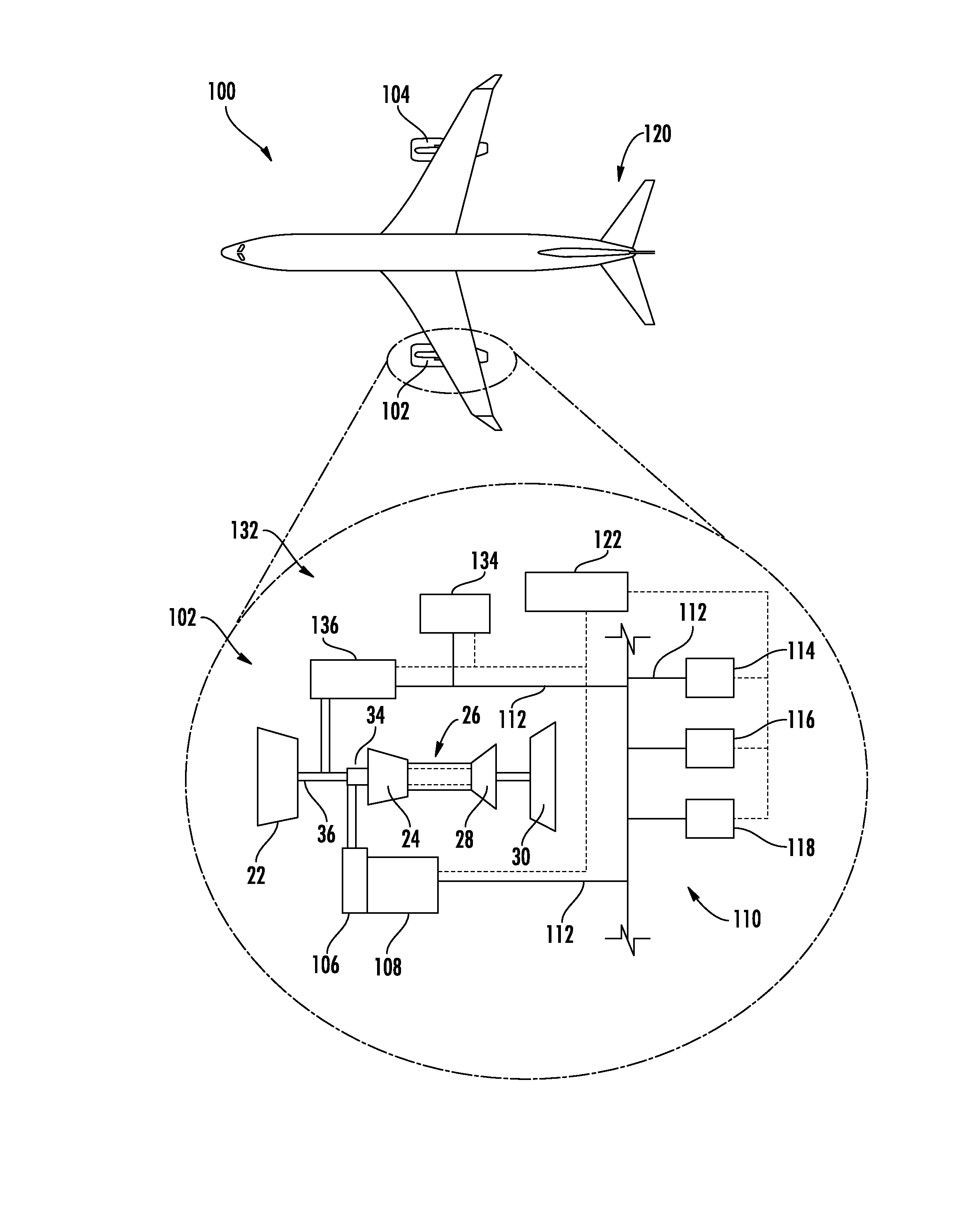
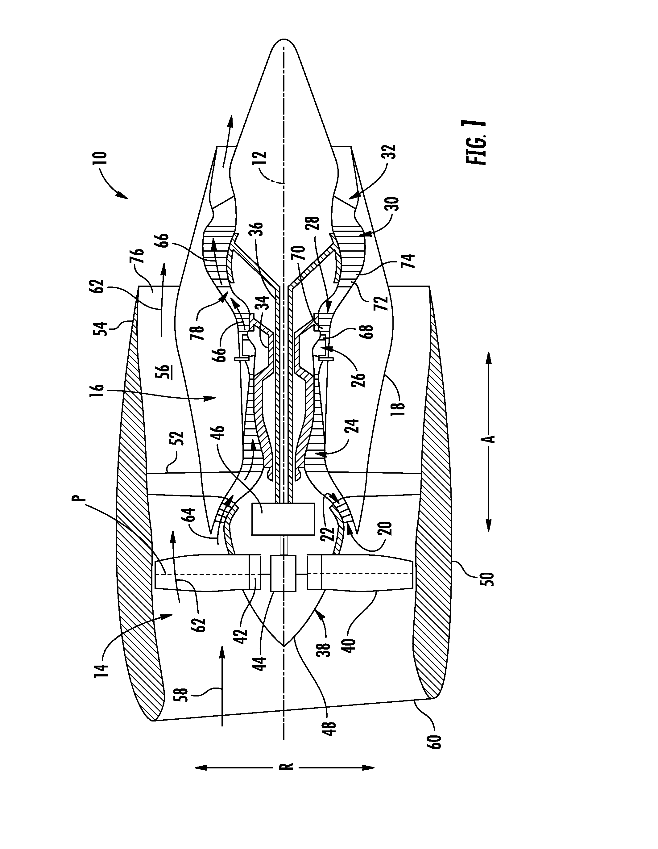
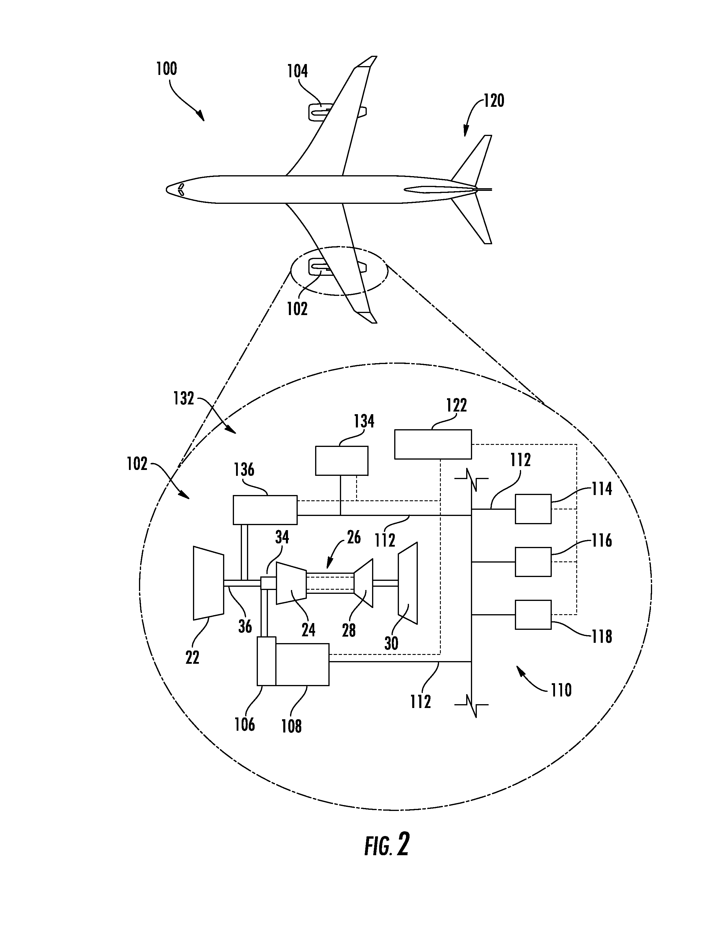
[0017]Reference will now be made in detail to present embodiments of the invention, one or more examples of which are illustrated in the accompanying drawings. The detailed description uses numerical and letter designations to refer to features in the drawings. Like or similar designations in the drawings and description have been used to refer to like or similar parts of the invention. As used herein, the terms “first”, “second”, and “third” may be used interchangeably to distinguish one component from another and are not intended to signify location or importance of the individual components. The terms “upstream” and “downstream” refer to the relative direction with respect to fluid flow in a fluid pathway. For example, “upstream” refers to the direction from which the fluid flows, and “downstream” refers to the direction to which the fluid flows.
[0018]Aspects of the present disclosure provide for a system (and method of operating the same) for a gas turbine engine that manages on...
PUM
 Abstract
Description
Claims
Application Information