Work vehicle

a technology for working vehicles and vehicles, applied in electrical control, applications, tractors, etc., can solve problems such as no conventional work vehicle configured to inform

Active Publication Date: 2017-02-16
YANMAR POWER TECHNOLOGY CO LTD
View PDF2 Cites 8 Cited by
  • Summary
  • Abstract
  • Description
  • Claims
  • Application Information

AI Technical Summary

Benefits of technology

[0013]The present invention has been conceived in view of such conventional art, and an object of the present invention is to provide a work vehicle capable of changing the speed of PTO rotary power transmitted from an engine to a PTO shaft by a multi-stage PTO

Problems solved by technology

However, there is no conventional work vehicle that is configured to inform in advance an operator of how the output rotational

Method used


Image

  • Work vehicle
  • Work vehicle
  • Work vehicle

Examples


first embodiment

[0040]Below, a preferable embodiment of the work vehicle of the present invention will now be described with reference to the appended drawings.

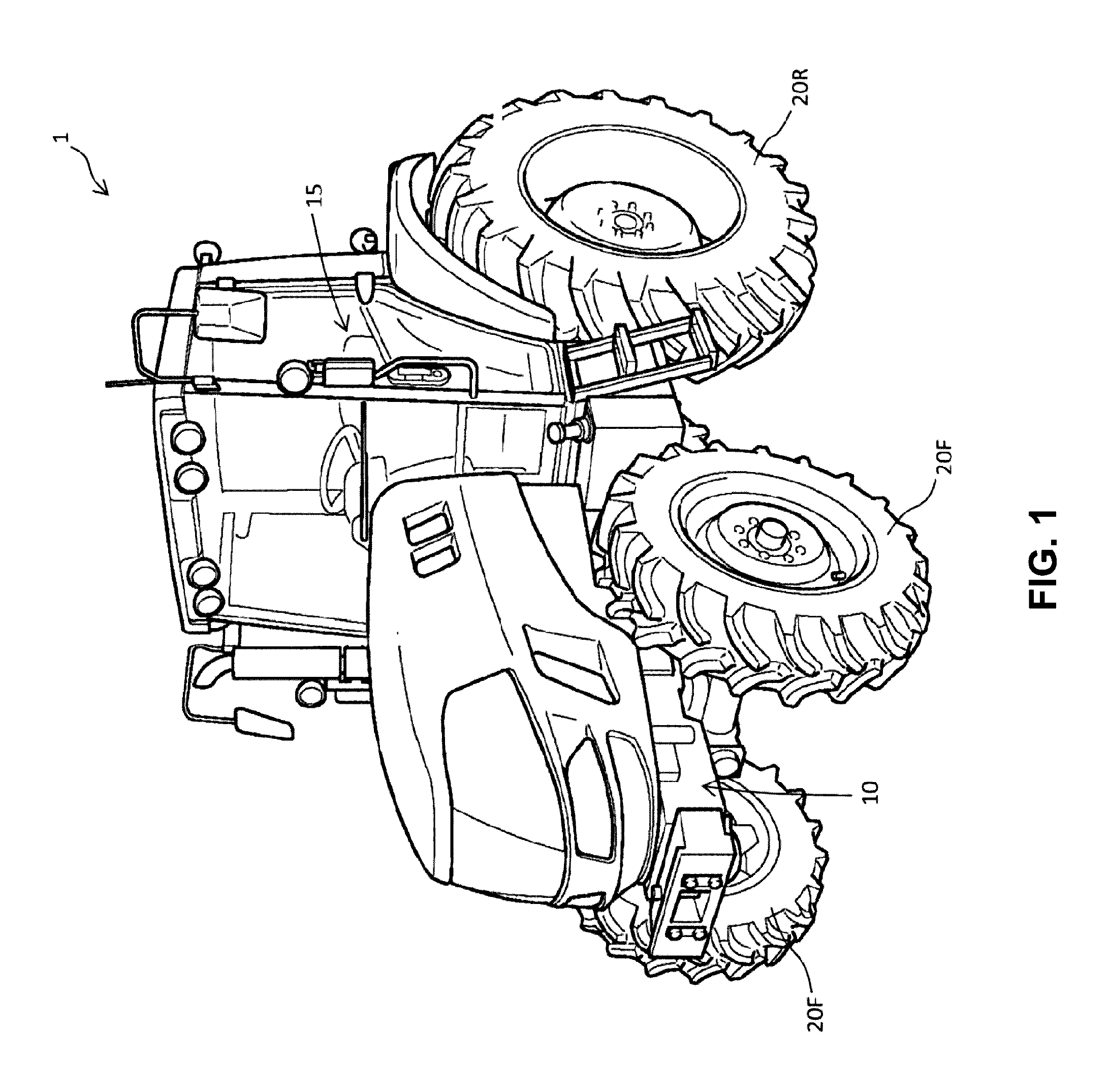
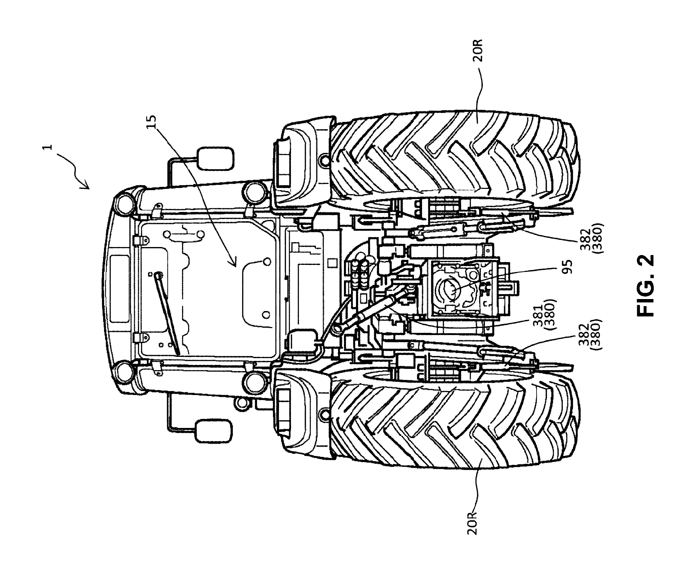
[0041]FIGS. 1 to 4 respectively show a perspective view, a rear view, a plan view, and a schematic power transmission diagram of a work vehicle 1 of this embodiment.

[0042]As shown in FIGS. 1 to 4, the work vehicle 1 of this embodiment is in the form of a tractor.

[0043]Specifically, as shown in FIGS. 1 to 4, the work vehicle 1 has a vehicle frame 10, a driver's seat 15 supported by the vehicle frame 10, an engine 50 supported by the vehicle frame 10, a pair of right and left front wheels 20F, a pair of right and left rear wheels 20R, a traveling-system power transmission structure 60 that transmits rotary power from the engine 50 to driving wheels, a PTO shaft 95 that outputs rotary power to outside, a PTO-system power transmission structure 80 that transmits rotary power from the engine 50 to the PTO shaft 95, a control device 100, and a fue...

second embodiment

[0187]Below, another embodiment of the work vehicle of the present invention will now be described with reference to the appended drawings.

[0188]In this embodiment, the same components as those in the first embodiment are given the same reference numbers, and descriptions thereof are omitted as appropriate.

[0189]The work vehicle of this embodiment is configured to be capable of enhancing the operability of various operation members.

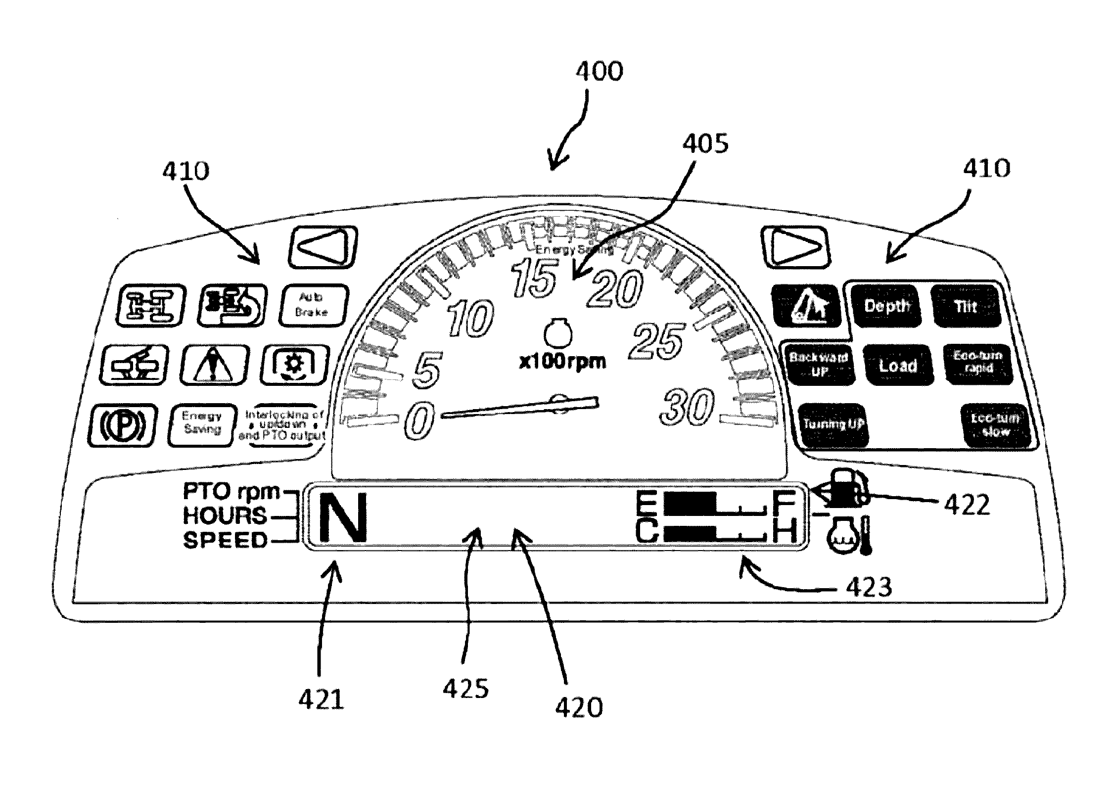
[0190]That is, providing a work vehicle such as a tractor with a liquid crystal display part in an instrument panel having a tachometer that shows the rotational speed of an engine and various indicator lamps is proposed (see, for example, JP 5138310B).

[0191]In the above conventional work vehicle, when a raising-lowering operation member for manually operating a raising-lowering actuator that raises or lowers an working device connected to the vehicle body is operated, the control device activates the raising-lowering actuator such that the working device...

third embodiment

[0241]Below, another embodiment of the work vehicle of the present invention will now be described with reference to the appended drawings.

[0242]In this embodiment, the same components as those in the first embodiment are given the same reference numbers, and descriptions thereof are omitted as appropriate.

[0243]The work vehicle of this embodiment is configured to be capable of efficiently informing an operator of information that the operator wishes to know and that changes in accordance with the traveling conditions and the work conditions.

[0244]That is, in a work vehicle such as a tractor, providing a liquid crystal display in an instrument panel having a tachometer that shows the rotational speed of an engine and various indicator lamps is proposed (see, for example, JP 2010-172267A).

[0245]Specifically, in the above conventional work vehicle, the liquid crystal display has a main speed-changing stage display area that shows the speed-changing stages of a main transmission, an au...


PUM


Abstract

In a work vehicle according to the present invention, a control device calculates, for each of a plurality of speed-changing stages in a PTO transmission, an expected maximum rotational speed of PTO rotary power that is output from the PTO shaft when an engine rotational speed changing operation member is operated to a maximum extent, and shows, in a listed manner, the calculated results in a liquid crystal display part of a display device. The present invention can inform an operator of the maximum rotational speed of PTO rotary power that is output from the PTO shaft for each speed-changing stage in the PTO transmission without performing a speed changing operation on the PTO transmission.

Description

FIELD OF THE INVENTION[0001]The present invention relates to a work vehicle, such as a tractor and a rice transplanter, equipped with a display device that shows information to an operator.BACKGROUND ART[0002]In utility vehicles such as tractors, it is conventional to provide a liquid crystal display part in an instrument panel that has a tachometer for indicating the rotational speed of an engine and various indicator lamps and show various information in the liquid crystal display part.[0003]For example, Patent Document 1 below discloses a work vehicle including an engine, a speed control lever operated to change the output rotational speed of the engine, a main transmission and an auxiliary transmission that change the speed of rotary power from the engine, a main shift lever and an auxiliary shift lever respectively operated to change the speed-changing status of the main transmission and the auxiliary transmission, an instrument panel including the liquid crystal display part, ...

Claims


Application Information

Patent Timeline
IPC IPC(8): F02D41/02B60K17/28F02D41/30B62D49/06F16H63/50F02D41/04B60R1/00B60K23/00
CPCF02D41/0215B60R1/00B60K17/28B60K23/00B62D49/0692B60K35/00F02D41/04F02D41/3005B60R2300/207A01B63/008F16H63/50B60W30/1888F02D41/021F02D31/007B60W2050/146B60K17/08B60Y2200/221B60Y2300/1888F16H2059/6815B60K37/02F16H2061/0218F16H2063/426A01B71/02B60W50/14B60W10/06B60W10/30B60W2050/0026B60W2510/30B60W2050/0027B60K2370/168B60K2370/61B60K2370/154B60W2540/215B60K2370/169B60K2370/171B60Y2400/92
Inventor UEDA, RYOUHEI
Owner YANMAR POWER TECHNOLOGY CO LTD
Why Eureka
Try Eureka