

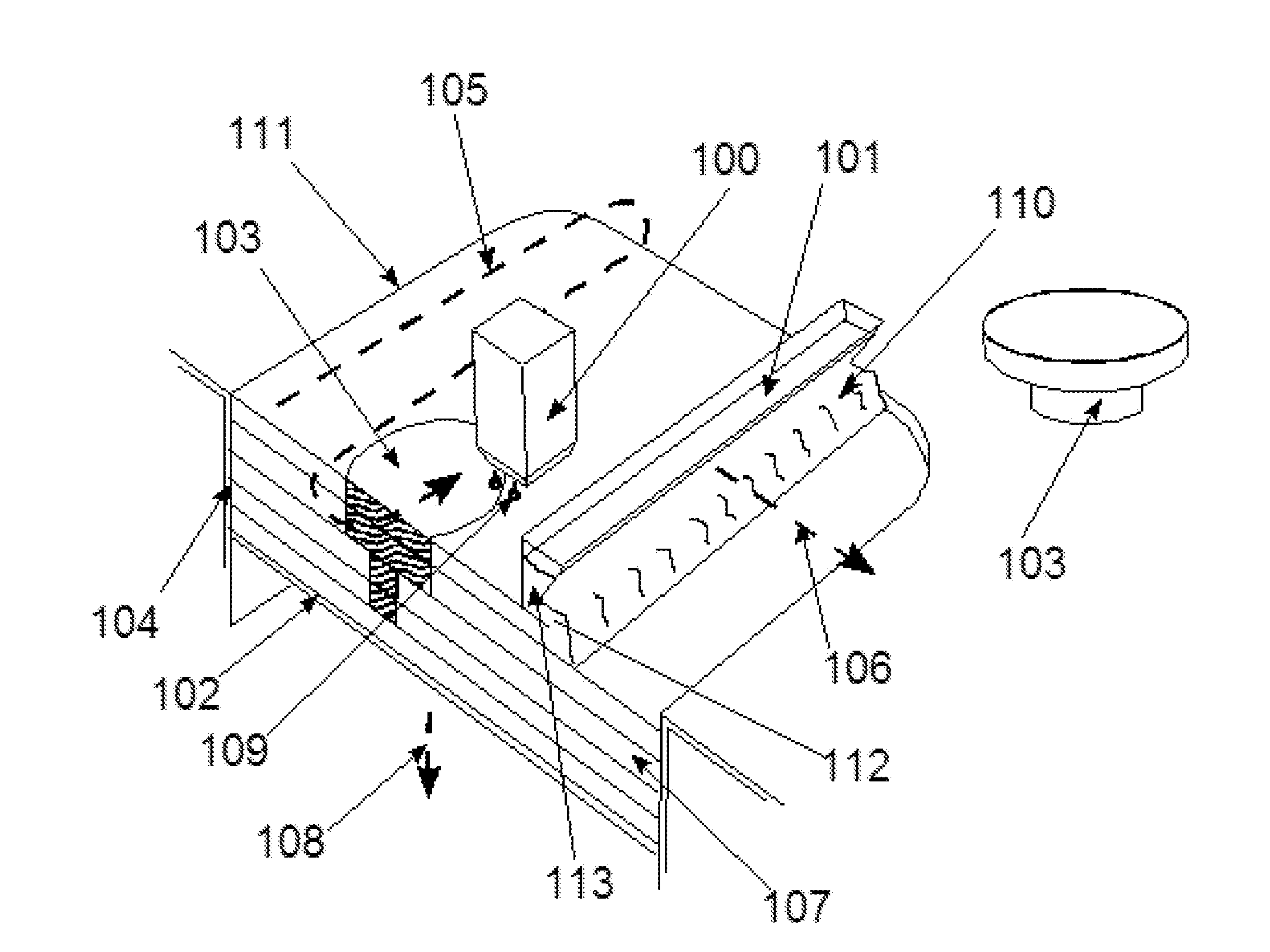
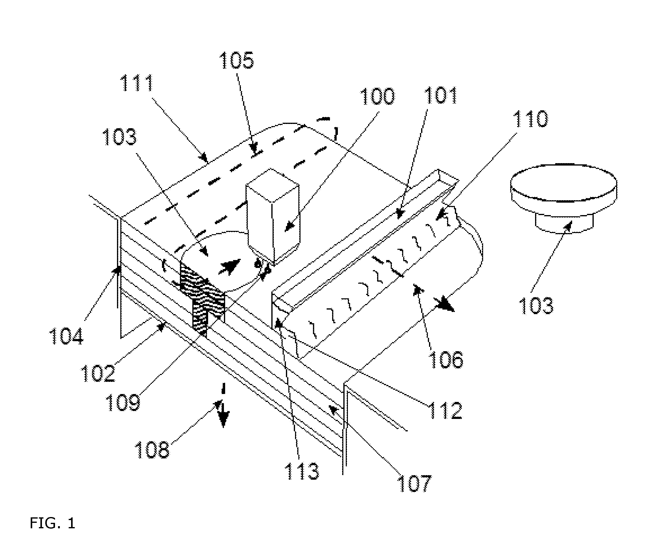
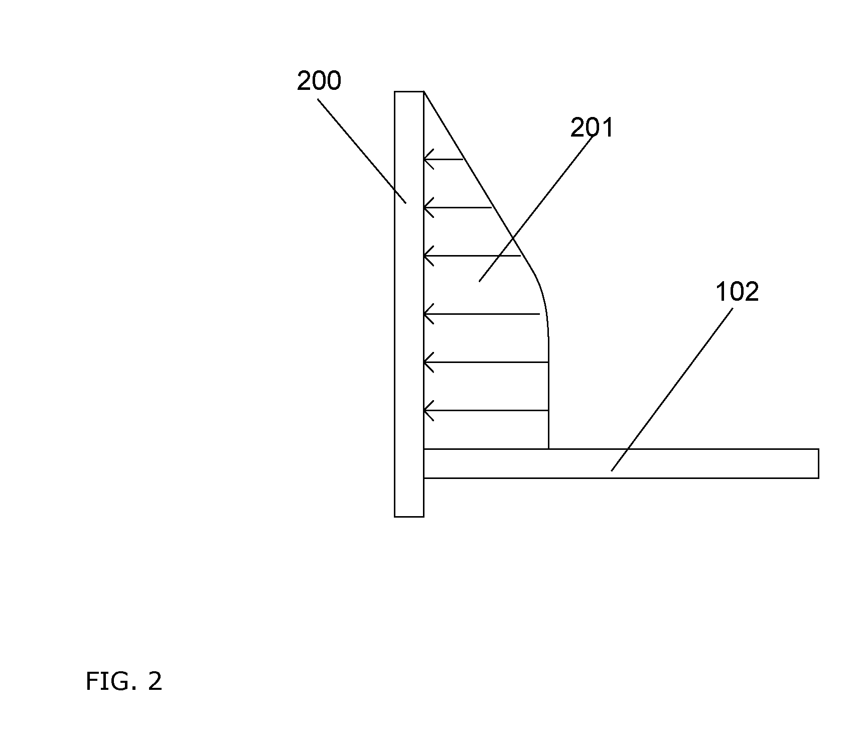
Interchangeable container wiht moveable side walls
a side wall and container technology, applied in the field of build containers or job boxes, can solve the problems of large machine size, precise and accurate production of components, and enormous difficulty in precise and even positioning, and achieve the effect of reducing friction problems
- Summary
- Abstract
- Description
- Claims
- Application Information
AI Technical Summary
Benefits of technology
Problems solved by technology
Method used
Image

Examples
Embodiment Construction
[0020]A number of terms in the invention are explained in greater detail below.
[0021]Within the meaning of the invention, “3D printing methods” relates to all methods known from the prior art which facilitate the construction of components in three-dimensional molds and are compatible with the described method components and devices. In particular, these are powder-based methods, for example SLS (selective laser sintering).
[0022]Within the meaning of the invention, “selective binder application” or “selective binder system application” may take place after each particulate material application or irregularly, depending on the requirements of the molded body and for the purpose of optimizing the production of the molded body, i.e., non-linearly and not in parallel after each particulate material application. “Selective binder application” or “selective binder system application” may thus be set individually and during the course of producing the molded body.
[0023]“Molded body” or “co...
PUM
| Property | Measurement | Unit |
|---|---|---|
| Force | aaaaa | aaaaa |
| Pressure | aaaaa | aaaaa |
| Flexibility | aaaaa | aaaaa |
Abstract
Description
Claims
Application Information