Lamp assembly

a technology for assembly and lamps, applied in the direction of instruments, lighting and heating apparatus, semiconductor devices for light sources, etc., can solve the problems of not always available or even allowed, bare far-field distribution and size of the emitting surface, and only suitable retrofit lamps

Inactive Publication Date: 2017-02-23
KONINKLJIJKE PHILIPS NV
View PDF5 Cites 18 Cited by
  • Summary
  • Abstract
  • Description
  • Claims
  • Application Information

AI Technical Summary

Benefits of technology

[0006]It is an object of the present invention to provide a retrofit lamp a

Problems solved by technology

That makes these retrofit lamps only suited for that specific application.
The major problem with these prior art LED retrofit lamps is that the bare far-field distribution and size of the emitting surface is not equal to the incandescent lamps t

Method used


Image

  • Lamp assembly
  • Lamp assembly
  • Lamp assembly

Examples


Embodiment Construction

[0020]The present invention will now be described more fully hereinafter with reference to the accompanying drawings, in which currently preferred embodiments of the invention are shown. The invention may, however, be embodied in many different forms and should not be construed as limited to the embodiments set forth herein. Rather, these embodiments are provided for thoroughness and completeness, and fully convey the scope of the invention to the skilled person.

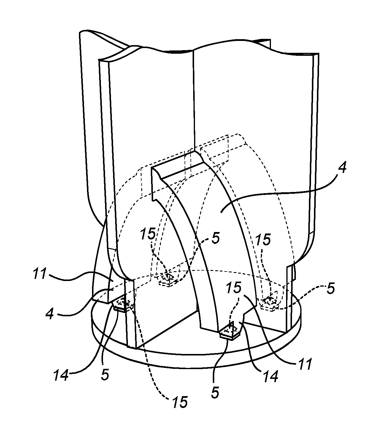
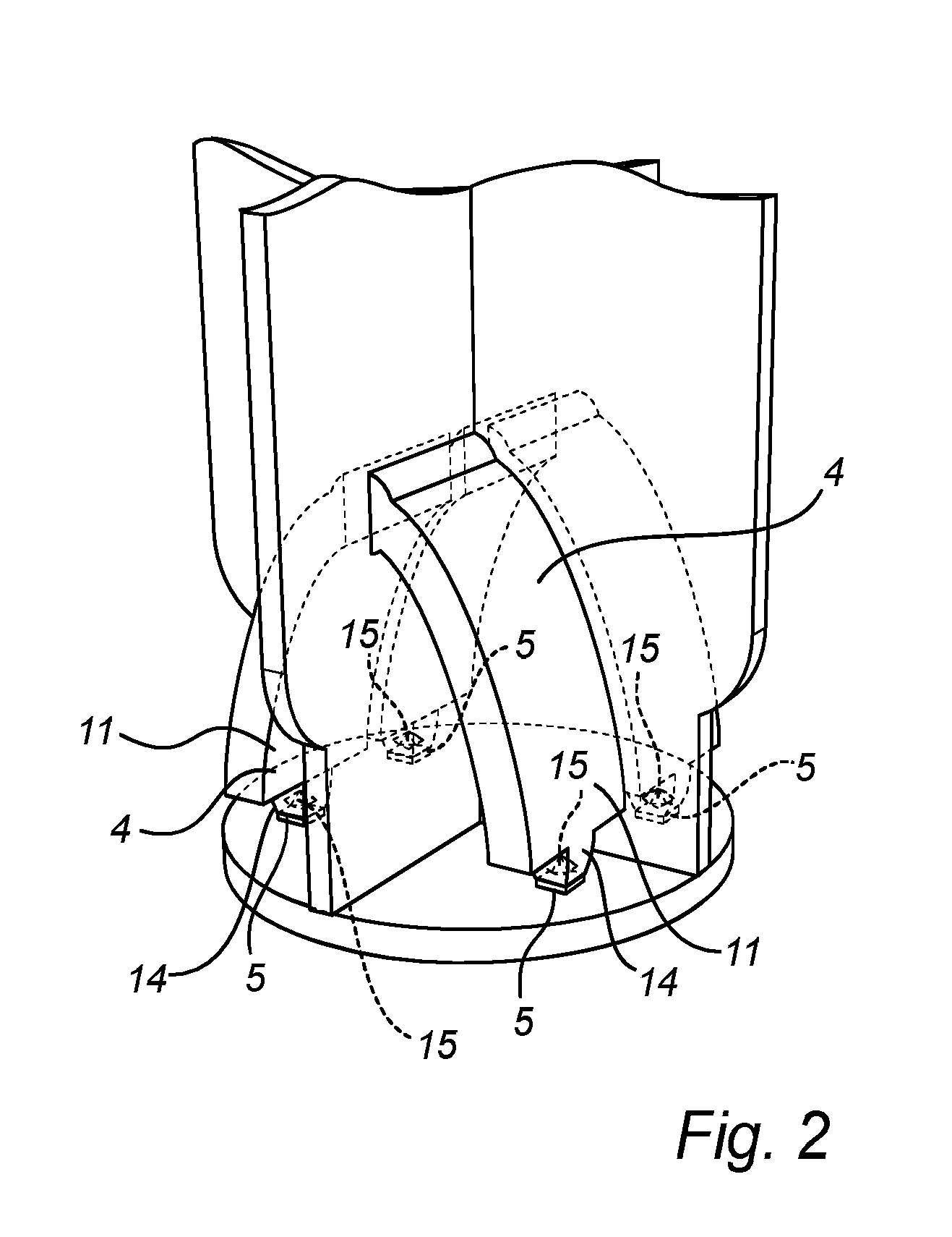
[0021]Making reference to FIG. 1, a general overview of one embodiment of the lamp assembly 1 is disclosed. The lamp assembly 1 comprises a support structure 2 supporting a light radiator 3 and a plurality of light guides 4. The light guides 4 have an elongated geometry extending between the light radiator 3 and a plurality of light sources 5 supported by the support structure 2. The light sources 5 do not need to be in optical contact with the light guides 4. Further, the light guides may not be in optical contact with the ...


PUM


Abstract

The invention relates to a lamp assembly (1) comprising a support structure (2) supporting a plurality of light sources (5), a light radiator (3) and a plurality of light guides (4). The light guides (4) have an elongated geometry extending between the plurality of light sources (5) and the light radiator (3) with an inlet portion (11) of each of the light guides (4) facing at least one of the plurality of light sources (5) and an outlet portion (12) of each of the light guides (4) facing the light radiator (3). The light radiator (3) is arranged to mimic a light filament of an incandescent lamp. The lamp assembly (1) further comprises a heat sink (16) having a fin-like geometry (18, 28) extending in the direction of the longitudinal centre axis L away from the light guides (4), said heat sink being thermally connected to the light guides (4).

Description

FIELD OF THE INVENTION[0001]The present invention relates to a lamp assembly comprising a support structure supporting a plurality of light sources, a light radiator and a plurality of light guides.BACKGROUND OF THE INVENTION[0002]Filament lamps are widely used in systems where there is additional optics, also so called secondary optics, to re-direct the light outputs in the required way. The secondary optics may be reflectors, lenses or combinations thereof. Many LED retrofit lamps use pre-knowledge of the secondary optics to offer sufficient light in the direction / position that is required for the specific application. That makes these retrofit lamps only suited for that specific application. It is also to be known that such specific retrofit lamps are not allowed in some regions such as e.g. EMEA.[0003]The major problem with these prior art LED retrofit lamps is that the bare far-field distribution and size of the emitting surface is not equal to the incandescent lamps that they ...

Claims


Application Information

Patent Timeline
IPC IPC(8): F21K9/232F21K9/61F21V7/00F21V29/76F21V5/00F21V8/00F21K9/64
CPCF21K9/232G02B6/0023G02B6/0073G02B6/0033F21Y2115/10F21K9/64F21V29/763F21V5/002F21V7/0066F21K9/61F21V5/10G02B6/0055G02B6/0068G02B6/0085G02B1/045
Inventor WEIJERS, ALDEGONDA LUCIATRALLI, ALDOHAENEN, LUDOVICUS JOHANNES LAMBERTUS
Owner KONINKLJIJKE PHILIPS NV
Why Eureka
Try Eureka