Ceramic heater, sensor element, and gas sensor

a ceramic heater and sensor element technology, applied in the field of ceramic heaters, to achieve the effect of prolonging the life of the heating elemen

Active Publication Date: 2017-02-23
NGK INSULATORS LTD
View PDF5 Cites 2 Cited by
  • Summary
  • Abstract
  • Description
  • Claims
  • Application Information

AI Technical Summary

Benefits of technology

[0023]Since the gas sensor includes the sensor element including the ceramic heater of any of the above-described embodiments, the gas sensor

Problems solved by technology

In these ceramic heaters, the heating element can be degraded by oxidation of conduct

Method used


Image

  • Ceramic heater, sensor element, and gas sensor
  • Ceramic heater, sensor element, and gas sensor
  • Ceramic heater, sensor element, and gas sensor

Examples


examples

[0103]Examples in which sensor elements were specifically manufactured will now be described. Experimental Examples 2 to 9 and 11 to 18 correspond to Examples of the present invention, and Experiment Examples 1 and 10 correspond to Comparative Examples. It should be noted that the invention is not limited to the examples below.

experimental examples 1 to 9

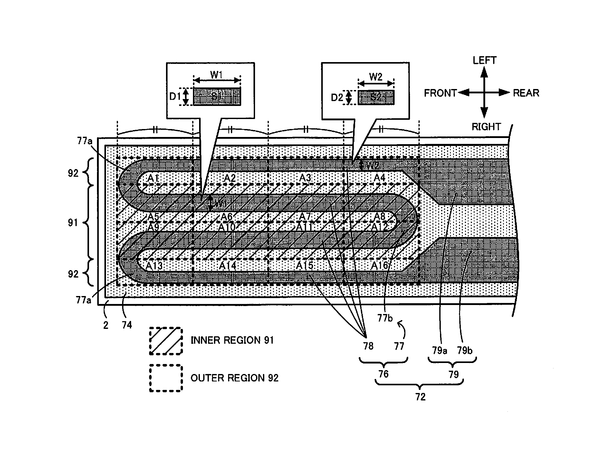
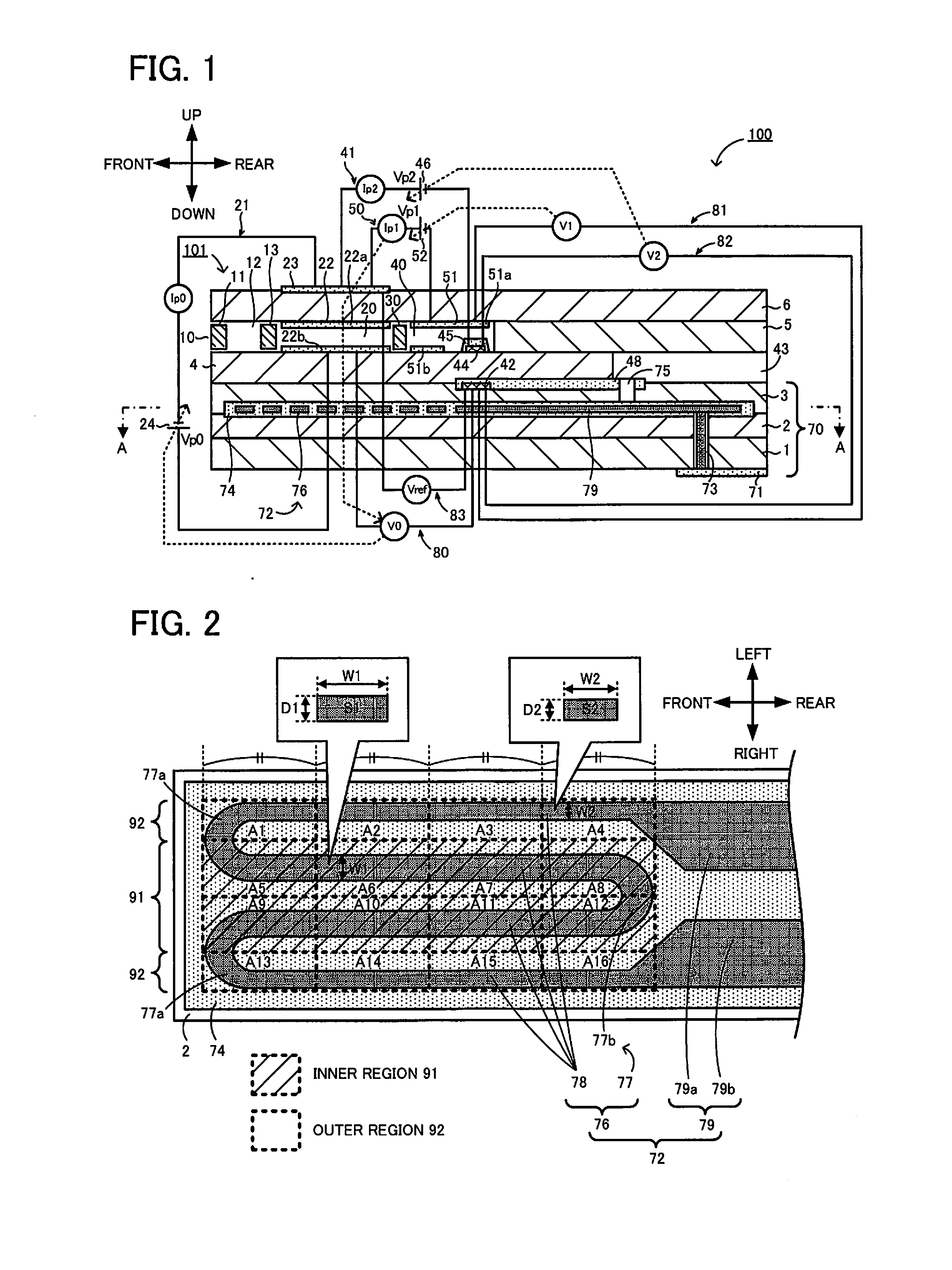
[0104]Sensor elements 101 as shown in FIGS. 1 and 2 were prepared as Experimental Examples 1 to 9 in accordance with the method for manufacturing the gas sensor 100 of the above-described embodiment. Experimental Examples 1 to 9 had the same structure except that the cross-sectional area ratio S2 / S1 in the inner region 91 and the outer regions 92 defined by the first method was varied as shown in Table 1 by varying the width W1 of the inner region 91. The sensor element 101 measured 67.5 mm in length in the front-rear direction, 4.25 mm in width in the left-right direction, and 1.45 mm in thickness in the vertical direction. In Experimental Example 1, the width W1 of the inner region 91 and the width W2 of the outer region 92 were each 0.25 mm. In Experimental Example 1, the thickness D1 of the inner region 91 and the thickness D2 of the outer region 92 were each 0.01 mm. For producing the sensor element 101, ceramic green sheets were formed of a mixture of zirconia particles contai...

experimental examples 10 to 18

[0105]Sensor elements 101 of Experimental Examples 10 to 18 were produced in the same manner as in Experimental Example 1 except that the volume resistivity ratio ρ1 / ρ2 of the inner region 91 and the outer regions 92 defined by the first method was varied as shown in Table 1. The volume resistivity ratio ρ1 / ρ2 was varied by varying the Pt content in the inner region 91. In each of Experimental Examples 10 to 18, widths W1 and W2 and thicknesses D1 and D2 were the same as in Experimental Example 1, and the cross-sectional area ratio S2 / S1 in Experimental Examples 10 to 18 was 1.00. In Experimental Examples 10 and 1, the cross-sectional area ratio S2 / S1 and the volume resistivity ratio ρ1 / ρ2 were the same.

[0106]The volume resistivity ρ1 in Experimental Examples 10 to 18 was measured using test pieces prepared as below. An insulating paste for the heater insulating layer 74 was applied by printing onto a ceramic green sheet that would be sintered into the second substrate layer 2. Subs...


PUM


Abstract

A heating element 76 of a heater section includes an inner region 91, having a lower resistance per unit length than an outer region 92 at one or more temperatures in the range of 700° C. to 900° C.

Description

BACKGROUND OF THE INVENTION[0001]1. Field of the Invention[0002]The present invention relates to a ceramic heater, a sensor element, and a gas sensor.[0003]2. Description of the Related Art[0004]There has been known ceramic heaters including a ceramic sheet and a heater pattern that is folded a plurality of times in the longitudinal direction of the ceramic sheet (for example, PTL 1). The heater pattern disclosed in PTL 1 includes straight conducting segments extending along the longitudinal direction, and a curved conducting segment connecting the straight conducting segments. Another type of ceramic heater has also been known which includes a pattern including straight portions extending along the short-length direction and a folded portion connecting the straight portions (for example, PTL 2).CITATION LISTPatent Literature[0005]PTL 1: Japanese Patent No. 4826461[0006]PTL 2: Japanese Patent No. 3571494SUMMARY OF THE INVENTION[0007]In these ceramic heaters, the heating element can ...

Claims


Application Information

Patent Timeline
IPC IPC(8): G01N27/406G01N27/407H05B3/26H05B1/02H05B3/00
CPCG01N27/4067H05B1/0247G01N27/4071H05B3/265G01N27/4073H05B3/0014
Inventor WATANABE, YUSUKEMURASE, TAKAOYASUI, MASASHI
Owner NGK INSULATORS LTD
Why Eureka
Try Eureka