Integrated software development environments, systems, methods, and memory models

a software development environment and memory model technology, applied in the field of computer program development technologies, can solve the problems of still having significant limitations, imposing strict rules on object instantiation, and code complex and difficult to maintain or refactor

Active Publication Date: 2017-02-23
INTEGRATOR SOFTWARE
View PDF17 Cites 43 Cited by
  • Summary
  • Abstract
  • Description
  • Claims
  • Application Information

AI Technical Summary

Benefits of technology

[0027]Since both data and the code that operates on that data are contained in the same kernel objects within an application, and since each value object has a label object whose value can be construed to be the name of that value object, when the code uses a variable whose name points to values in the data, the “name” of the variable can be a reference to any label of the value objects desired for the algorithm. When the programmer defines a variable by “pointing” to a label, the system software follows the references from that label to the Terminal Value where the “name” is stored and substitutes the UID or other reference of this Terminal Value into the code. Then, at runtime, as the code is retrieved to be assembled into an executable file, the system software will retrieve this Terminal Value and insert it into the code as the variable name. In this fashion, even when the values used as names (metadata) for the value objects (data) are changed, the code will continue to execute on the same values. In this way, both the data structure and the software algorithms are fully normalized and integrated and up-to-date.

Problems solved by technology

Although such development environments are very powerful, they still have significant limitations.
One limitation of known development environments, especially object oriented systems, is that they enforce strict rules on object instantiation.
Thus, an application can have hundreds or thousands of different types of objects rendering the code quite complex and difficult to maintain or refactor.
Examples of such complexity include how and when objects are displayed, how the display screen is populated, and how changes to data objects and their contents are displayed.
Another limitation often encountered when using complex development environments is the lack of support to display visual representations of the semantics of the programming code.
Such systems allow developers to display source code in a graphical setting, but fail to provide semantic and syntactical information in a unified fashion to ease development of software.
However, these development environments have only limited abilities to change the views of the data and algorithms, which can be cumbersome to accomplish and are not saved as views into the current application, but only as instances of the application.
Therefore the combination of stages and intermediate data values become bulky and difficult to navigate.
The user can only interact with the data through middleware, and this restricts the functionality available.
Although some database packages expose this middleware to provide a user interface, the packages still require extensive programming.

Method used


Image

  • Integrated software development environments, systems, methods, and memory models
  • Integrated software development environments, systems, methods, and memory models
  • Integrated software development environments, systems, methods, and memory models

Examples


Embodiment Construction

[0067]Throughout the following discussion, numerous references will be made regarding servers, services, interfaces, engines, modules, clients, peers, portals, platforms, or other systems formed from computing devices. It should be appreciated that the use of such terms is deemed to represent one or more computing devices having at least one processor (e.g., ASIC, FPGA, DSP, x86, ARM, ColdFire, GPU, multi-core processors, etc.) configured to execute software instructions stored on a computer readable tangible, non-transitory medium (e.g., hard drive, solid state drive, RAM, flash, ROM, etc.). For example, a server can include one or more computers operating as a web server, database server, or other type of computer server in a manner to fulfill described roles, responsibilities, or functions. One should further appreciate the disclosed computer-based algorithms, processes, methods, or other types of instruction sets can be embodied as a computer program product comprising a non-tra...


PUM


Abstract

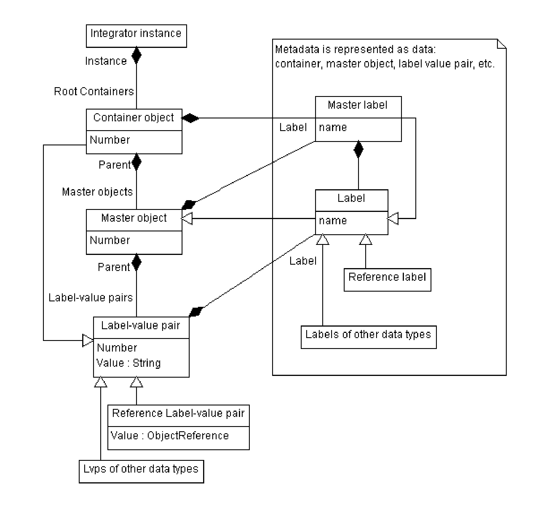
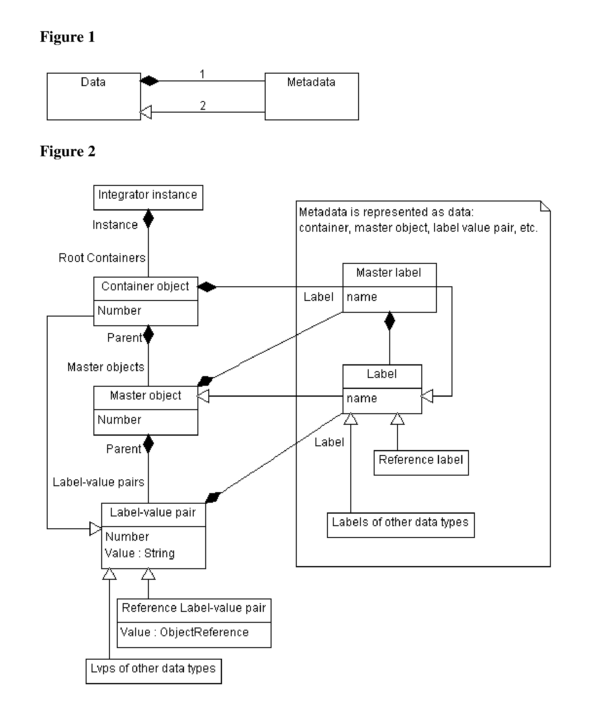
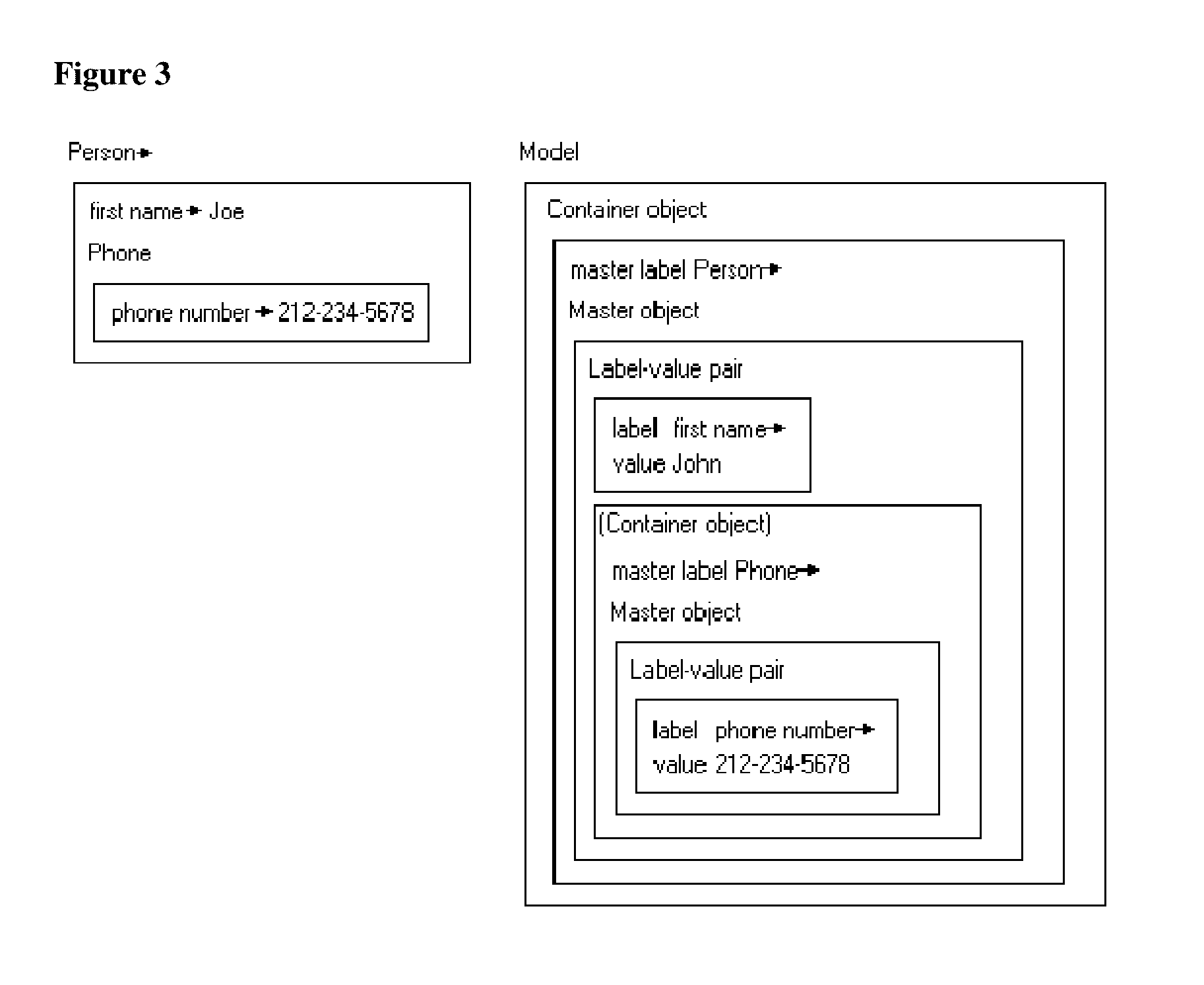
A data schema stores both data and metadata as data in a hierarchical, extensible schema made of three classes of objects. The data schema includes algorithms that generate the data schema and provide the functionality. Container object hold master objects, which represent items in a collection. Master objects hold label-value pairs, having a label portion that provides metadata, and having a value portion that holds the data. The label portion references a second label-value pair, in which the value portion holds the metadata as data, which is retrieved at runtime. Label-value pairs may reference a child container object in master objects to create a hierarchy. The schema can retrieve data and data structures from other databases; multiple databases of different formats can be joined. Software can be stored as data and shown as active flowcharts. A graphical interface can be generated in multiple display modes, including in websites.

Description

[0001]This application claims priority to U.S. provisional patent application Ser. No. 62 / 207,305, filed Aug. 19, 2015.FIELD OF THE INVENTION[0002]The field of the invention is computer program development technologies.BACKGROUND[0003]The following description includes information that may be useful in understanding the present invention. It is not an admission that any of the information provided herein is prior art or relevant to the presently claimed invention, or that any publication specifically or implicitly referenced is prior art.[0004]Numerous computer programming environments exist capable of supporting many different programming languages. For example, Microsoft's Visual Studio® integrated development environment (IDE) allows developers to create software application in many different computing languages (e.g., C#, C++, F#, Python, etc.) on the Microsoft .NET® platform. The .NET platform is able to convert a high level language to a low level intermediary language, which ...

Claims


Application Information

Patent Timeline
Patent Type & Authority Applications(United States)
IPC IPC(8): G06F9/44G06F17/30G06V30/224
CPCG06F8/34G06F17/30598G06F17/30342G06F17/30528G06F17/30554G06F16/211G06F16/248G06F16/285G06F16/2291G06F16/24575
Inventor GARIPOV, OLEG
Owner INTEGRATOR SOFTWARE
Why Eureka
Try Eureka