Eureka AIR delivers breakthrough ideas for toughest innovation challenges, trusted by R&D personnel around the world.

Buffer cache device method for managing the same and applying system thereof

a buffer cache and cache technology, applied in the direction of memory address/allocation/relocation, input/output to record carriers, instruments, etc., can solve the problems of deteriorating system operation efficiency, data stored in the dram cache may be lost, file system may enter an inconsistent state, etc., to improve the performance of the embedded system, improve the write access of the pcm involved, and reduce the write latency due to the write power limitation of the pcm

Inactive Publication Date: 2017-02-23
MACRONIX INT CO LTD
View PDF7 Cites 4 Cited by
  • Summary
  • Abstract
  • Description
  • Claims
  • Application Information

AI Technical Summary

Benefits of technology

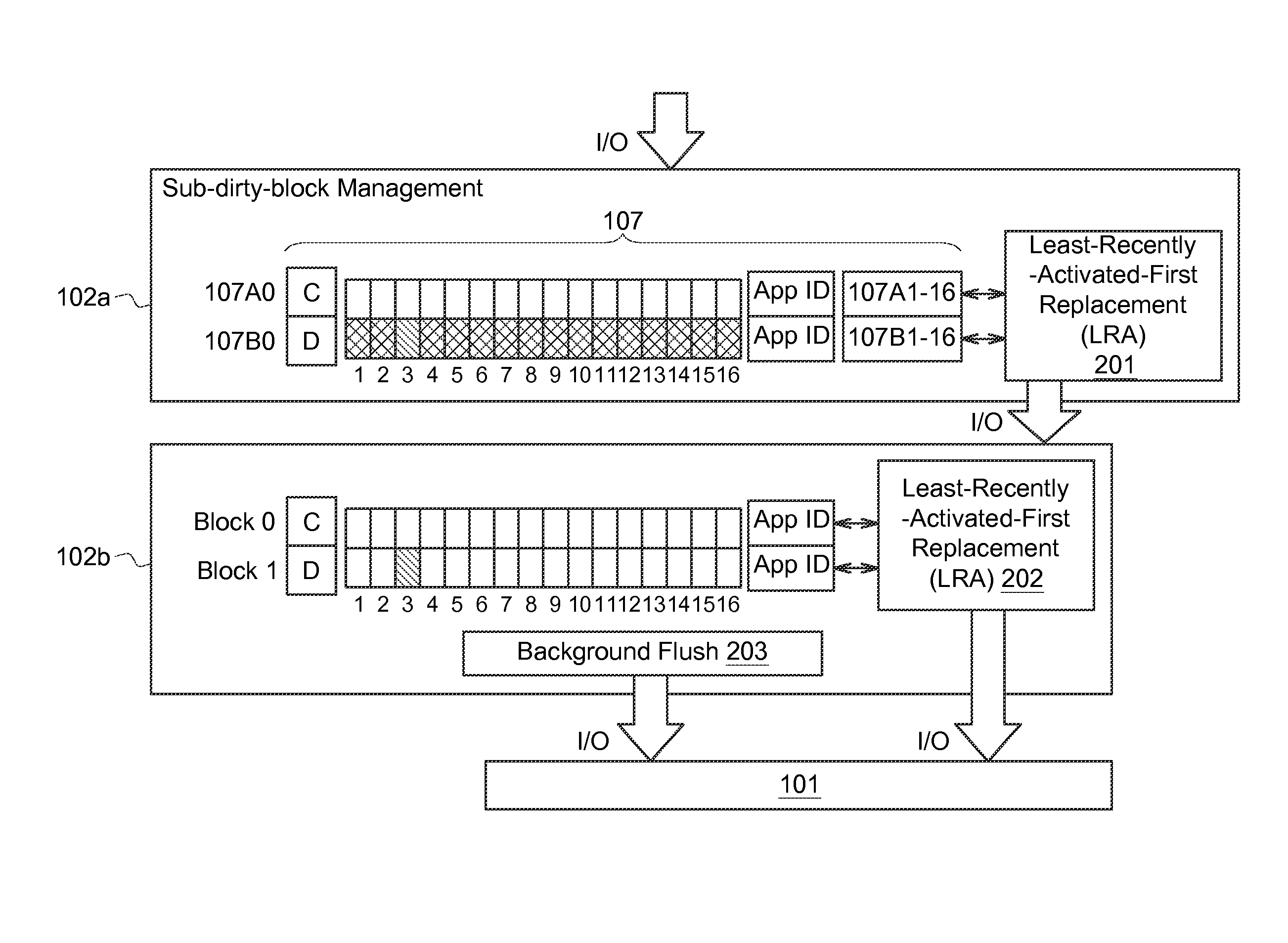
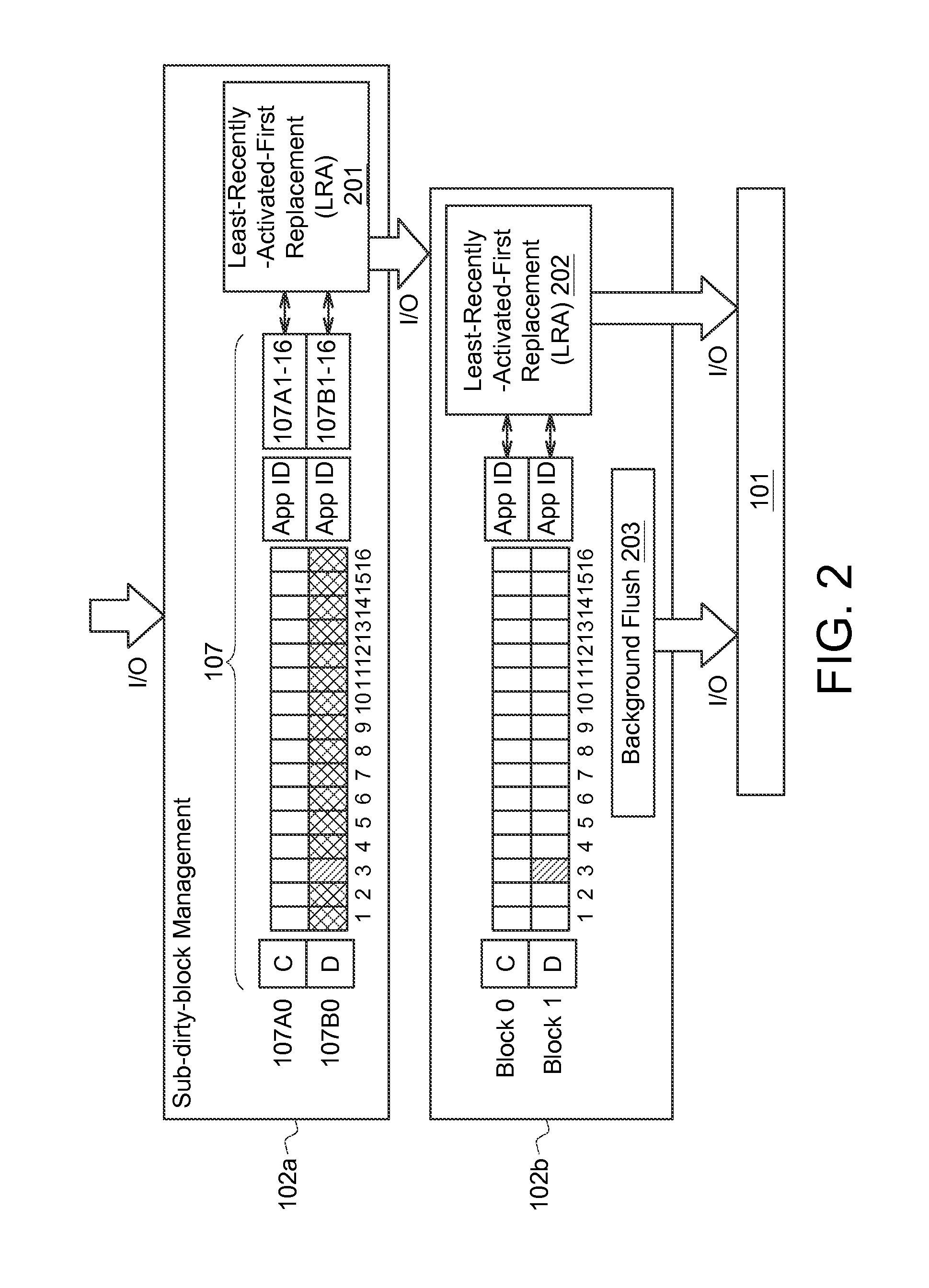
The present invention provides a hybrid buffer cache device and application system with multiple cache memories that solve the problem of file system inconsistency. The device includes a first-level cache memory and a second-level cache memory with different memory cell architectures. The data from applications is stored in the first-level cache memory and then written to the second-level cache memory in a hierarchical write-back process. The device also introduces sub-dirty block management to improve performance by alleviating write latency due to the write power limitation of PCM. Additionally, a least-recently activated (LRA) data replacement policy is applied to the buffer cache operation to improve system performance.

Problems solved by technology

However, the DRAM is a volatile memory, data stored in the DRAM cache may loss when the power supply is removed, and the file system may enter an inconsistent state upon sudden system crashes.
However, this approach may deteriorated the system operation efficiency.
However, PCM has some disadvantages such as longer write latency and shorter lifetime than DRAM.
Furthermore, PCM can only write a limited data bytes, such as at most 32 bytes, in parallel due to the write power limitation, this may prolong serious write latency compared to the DRAM buffer cache.
It seems to not be a proper approach to use PCM as the sole storage media of a buffer cache device.

Method used


Image

  • Buffer cache device method for managing the same and applying system thereof
  • Buffer cache device method for managing the same and applying system thereof
  • Buffer cache device method for managing the same and applying system thereof

Examples


Embodiment Construction

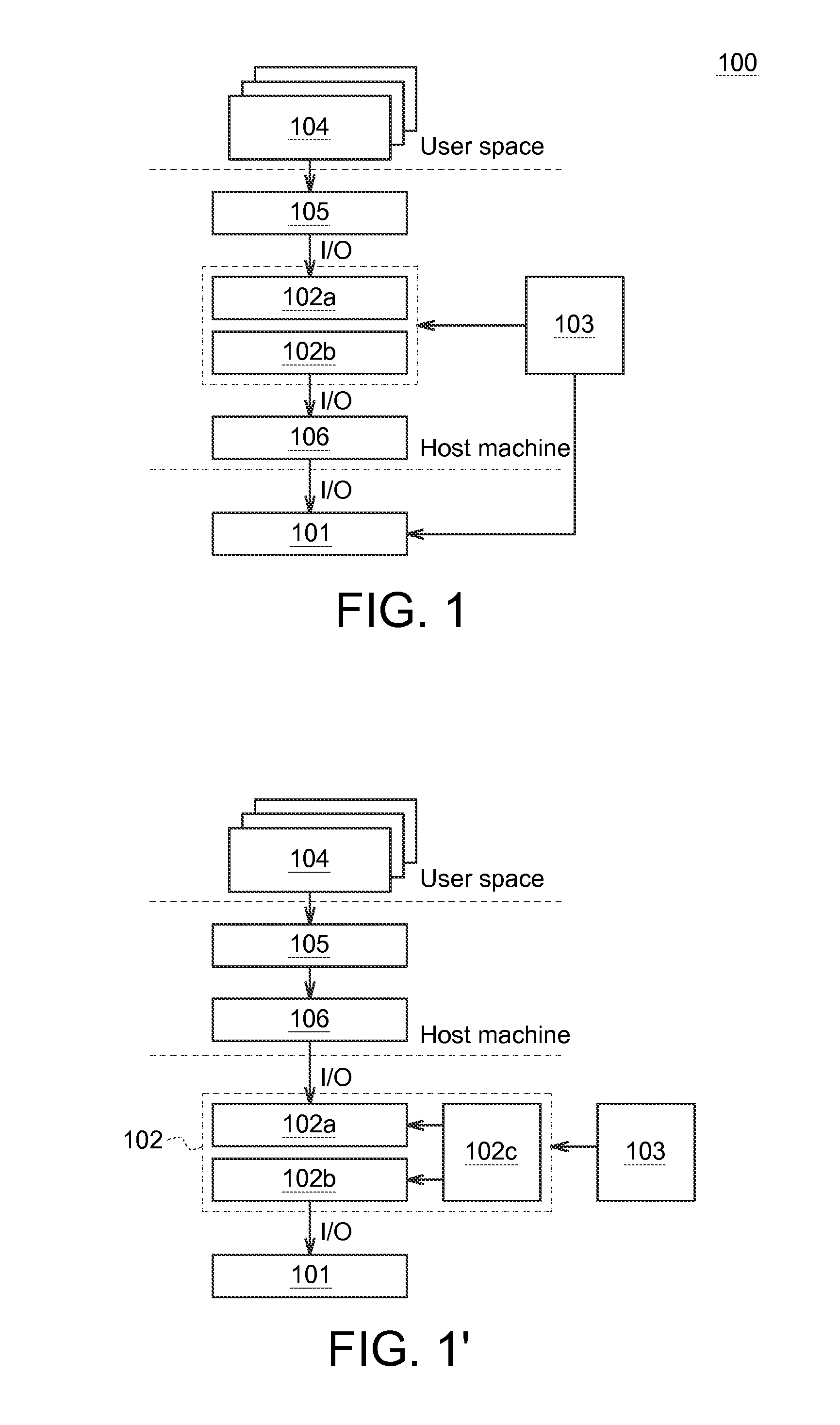
[0021]The embodiments as illustrated below provide a buffer cache device, the method thereof for managing the same and the applying system thereof to solve the problems of file system inconsistency and write latency resulted from using either DRAM or PCM as the sole storage media in a buffer cache device. The present invention will now be described more specifically with reference to the following embodiments illustrating the structure and arrangements thereof.

[0022]It is to be noted that the following descriptions of preferred embodiments of this invention are presented herein for purpose of illustration and description only. It is not intended to be exhaustive or to be limited to the precise form disclosed. Also, it is also important to point out that there may be other features, elements, steps and parameters for implementing the embodiments of the present disclosure which are not specifically illustrated. Thus, the specification and the drawings are to be regard as an illustrati...


PUM


Abstract

A buffer cache device used to get at least one data from at least one application is provided, wherein the buffer cache device includes a first-level cache memory, a second-level cache memory and a controller. The first-level cache memory is used to receive and store the data. The second-level cache memory has a memory cell architecture different from that of the first-level cache memory. The controller is used to write the data stored in the first-level cache memory into the second-level cache memory.

Description

BACKGROUND[0001]Technical Field[0002]The disclosure relates in generally related to a buffer cache device, the method for managing the same and the application system thereof, and more particularly to a hybrid buffer cache device having multi-level cache memories, the method for managing the same and the application system thereof.[0003]Description of the Related Art[0004]Buffer cache is the technique of storing a copy of data temporarily in rapidly-accessible storage media local to the processing unit (PU) and separate from the bulk / main storage device to provide the PU a quick access without referring back to the bulk storage device when the data is frequently requested, so as to improve the response / execution time of the operation system.[0005]Typically, a traditional buffer cache device applies a dynamic random access memory (DRAM) as the rapidly-accessible storage media. However, the DRAM is a volatile memory, data stored in the DRAM cache may loss when the power supply is remo...

Claims


Application Information

Patent Timeline
Patent Type & Authority Applications(United States)
IPC IPC(8): G06F12/08G06F3/06
CPCG06F12/0897G06F3/0604G06F2212/225G06F3/0685G06F3/0656G06F12/0804G06F12/0891G06F2212/1044
Inventor LIN, YE-JYUNLI, HSIANG-PANGWANG, CHENG-YUANYANG, CHIA-LIN
Owner MACRONIX INT CO LTD
Why Eureka
Eureka Blog
Learn More