
Electric field time-grating linear displacement sensors based on single row multilayer structure

a time-grating linear displacement and sensor technology, applied in the direction of measuring devices, instruments, using electrical means, etc., can solve the problems of increasing measurement errors, affecting the accuracy of measurement, and affecting the consistency of measurement, so as to achieve high precision, low power consumption, and simple structure

Active Publication Date: 2019-12-03
GENERTEC GUOCE TIME GRATING TECH CO LTD
View PDF31 Cites 0 Cited by
  • Summary
  • Abstract
  • Description
  • Claims
  • Application Information

AI Technical Summary

Benefits of technology

The present invention provides an electric field type time-grating linear displacement sensor based on a single row multilayer structure. It solves the problems of interference between signals of the two rows of electrodes and inconsistency between the two rows of electrodes resulting from production or installation. It is able to directly obtain the traveling wave signal based on electric field coupling mechanism without an adding circuit, reducing measurement errors and simplifying system structure. The moving ruler electrodes have a double sinusoidal shape formed by two vertically symmetrical sinusoidal shapes connected via a rectangular lead, which can completely cover the facing four excitation signal leads of the fixed ruler electrodes. The sensor has the advantages of low power consumption, high precision, achieving displacement measurement with nanometer precision, simple structure, low requirements for mechanical installation accuracy, and high stability in industrial applications.

Problems solved by technology

However, it has been noted that the two rows of electrode signals may interfere with each other, which may lead to an increase of measurement errors, and thus hinder further improvements in its measurement accuracy.
On the other hand, concerning its manufacturing process, it is difficult to ensure a consistency between the two rows of electrodes; In addition, concerning its installation, it is difficult to ensure consistent electric field coupling strengths between the two rows of electrodes as well.
As a result, the foregoing issues may result in an inconsistency in amplitude of the generated two channels of standing wave signals, which will lead to measurement errors and thus compromise its applications in industrial field.

Method used


Image

  • Electric field time-grating linear displacement sensors based on single row multilayer structure
  • Electric field time-grating linear displacement sensors based on single row multilayer structure
  • Electric field time-grating linear displacement sensors based on single row multilayer structure

Examples


Embodiment Construction

[0023]The present invention will be further described in reference to the accompanying drawings.

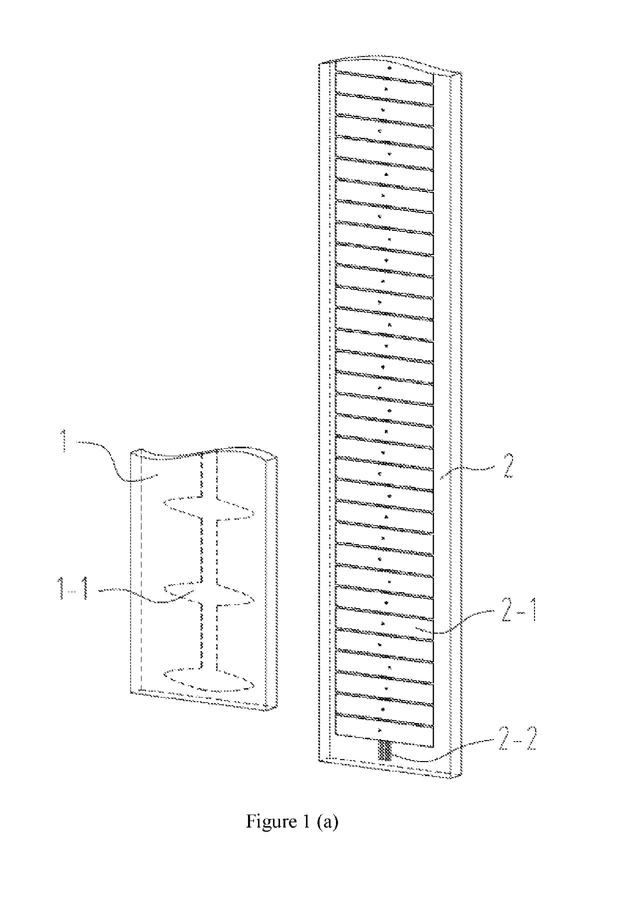
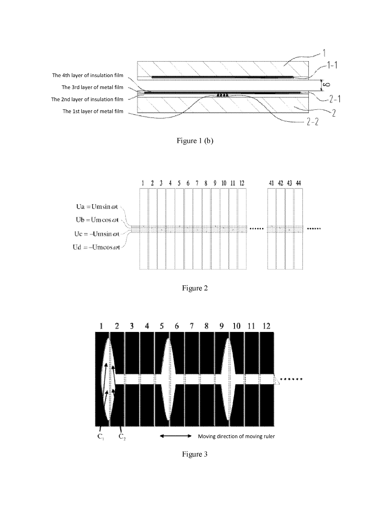
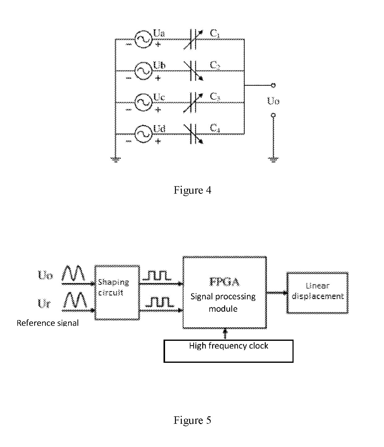
[0024]As shown in FIG. 1 (a), FIG. 1 (b), FIG. 2, FIG. 3 and FIG. 4, the proposed sensor comprises two parts, namely a fixed ruler 1 and a moving ruler 2 which are formed by a ceramic material; and the ceramic surface has been sprayed with a layer of iron nickel alloy as the electrodes thereof.

[0025]The moving ruler 1 has 12 induced electrodes in total, which is referred to as the induced electrode 1-1. The size of each induced electrode is 18 mm*1.1 mm. In addition, the shape of the moving ruler electrode is formed by the area defined by the sine curve within the range [0, π] and the x-axis and the area defined by the sine curve within the range [π, 2π] and the x-axis. Further, the rectangular lead with a width of 1.8 mm connected the moving ruler electrodes together.

[0026]The fixed ruler body is covered by four layers of medium films. The first layer is a metal film. The second layer is...


PUM


Abstract

An electric field type time-grating linear displacement sensor based on a single row multilayer structure, including a moving ruler and a fixed ruler. The moving ruler having a row of induced electrodes and the fixed ruler having a row of excitation electrodes.

Description

RELATED APPLICATIONS[0001]This application is a continuation of copending International Application No.: PCT / CN2014 / 083125, filed Jul. 28, 2014, which is in incorporated herein by reference in its entirety, and additionally claims priority to Chinese Application No.: 201410102437.6, filed Mar. 19, 2014, which is also incorporated herein by reference in its entirety.TECHNICAL FIELD[0002]The present invention relates to sensors for precision linear displacement measurement.BACKGROUND ART[0003]In the technical fields of precision linear displacement measurement, in recent years, a new type of time-grating sensor has been developed in China. This time-grating sensor uses a clock pulse as the reference for displacement measurements. And based on the foregoing, a time-grating linear displacement sensor based on alternating electric field has been further developed. The patent application document for this sensor has been published on Dec. 21, 2011 with its Title of Invention as “Time-grat...

Claims


Application Information

Patent Timeline
Patent Type & Authority Patents(United States)
IPC IPC(8): G01D5/241G01B7/02
CPCG01B7/02G01D5/241G01D5/2415
Inventor LIU, XIAOKANGPENG, DONGLINPENG, KAIZHENG, FANGYAN
Owner GENERTEC GUOCE TIME GRATING TECH CO LTD
Learn More