

Mobile device human body scanning and 3D model creation and analysis
- Summary
- Abstract
- Description
- Claims
- Application Information
AI Technical Summary
Benefits of technology
Problems solved by technology
Method used
Image

Examples
Embodiment Construction
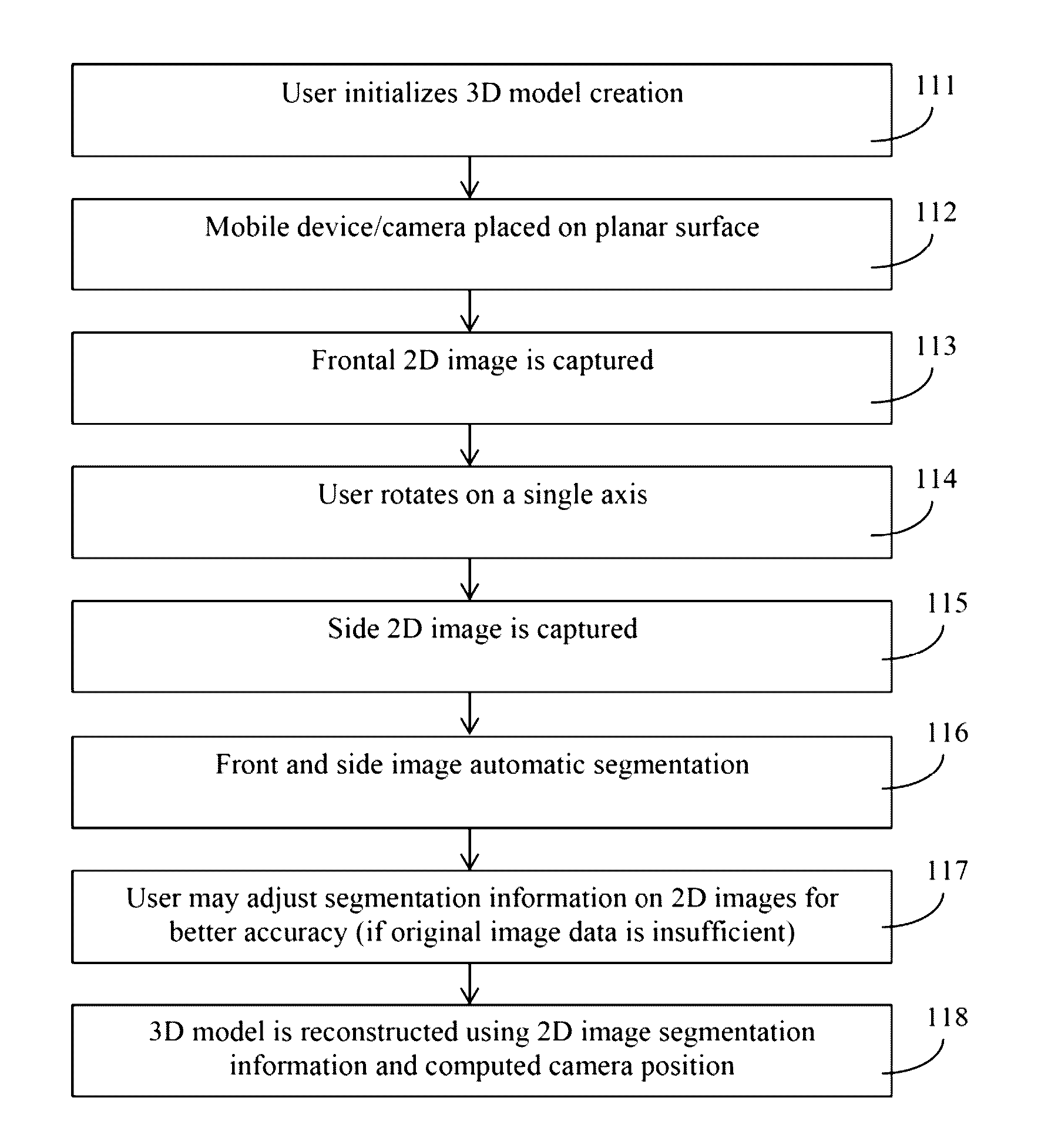
[0042]The invention comprises a method which uses a single 2D camera, for example, a mobile device's camera, to take multiple (i.e., two or more) 2D pictures and make a 3D body model. The method requires 2 images of a body, from which the method creates a 3D model, and without requiring a depth measurement. The camera is ideally built-in to the mobile device. In one embodiment the camera is external to the mobile device and connected via a wired or wireless connection. The mobile device is ideally a smartphone, PDA, tablet, or other small mobile device, but it could also be a laptop, desktop computer, or other device equipped with a camera. For higher accuracy of the 3D reconstruction, invention may further comprise using a built-in accelerometer providing angles for camera positioning. In some embodiments, the method comprises taking three or more 2D pictures to form a 3D body model.
[0043]During initial 2D image capture, the subject is positioned in two poses (manners) in front of ...
PUM
 Abstract
Description
Claims
Application Information