Control arm

Inactive Publication Date: 2017-03-02
RAUFOSS TECH AS
View PDF3 Cites 9 Cited by
  • Summary
  • Abstract
  • Description
  • Claims
  • Application Information

AI Technical Summary

Benefits of technology

[0008]This production method provides an arm with an elongated grain structure in the alumi

Problems solved by technology

However, these steel arms are relatively heavy, even though being hollow.
Further the hollow steel arms are apt to corrode.
Another disadvantage of these arms is the involved production process, including pressing, punching, welding

Method used


Image

  • Control arm
  • Control arm
  • Control arm

Examples


Embodiment Construction

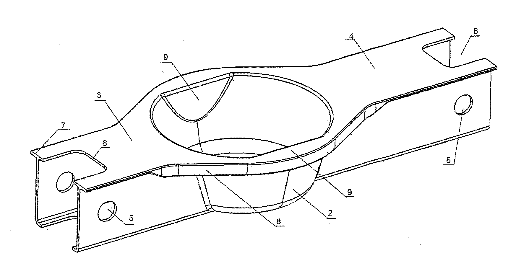
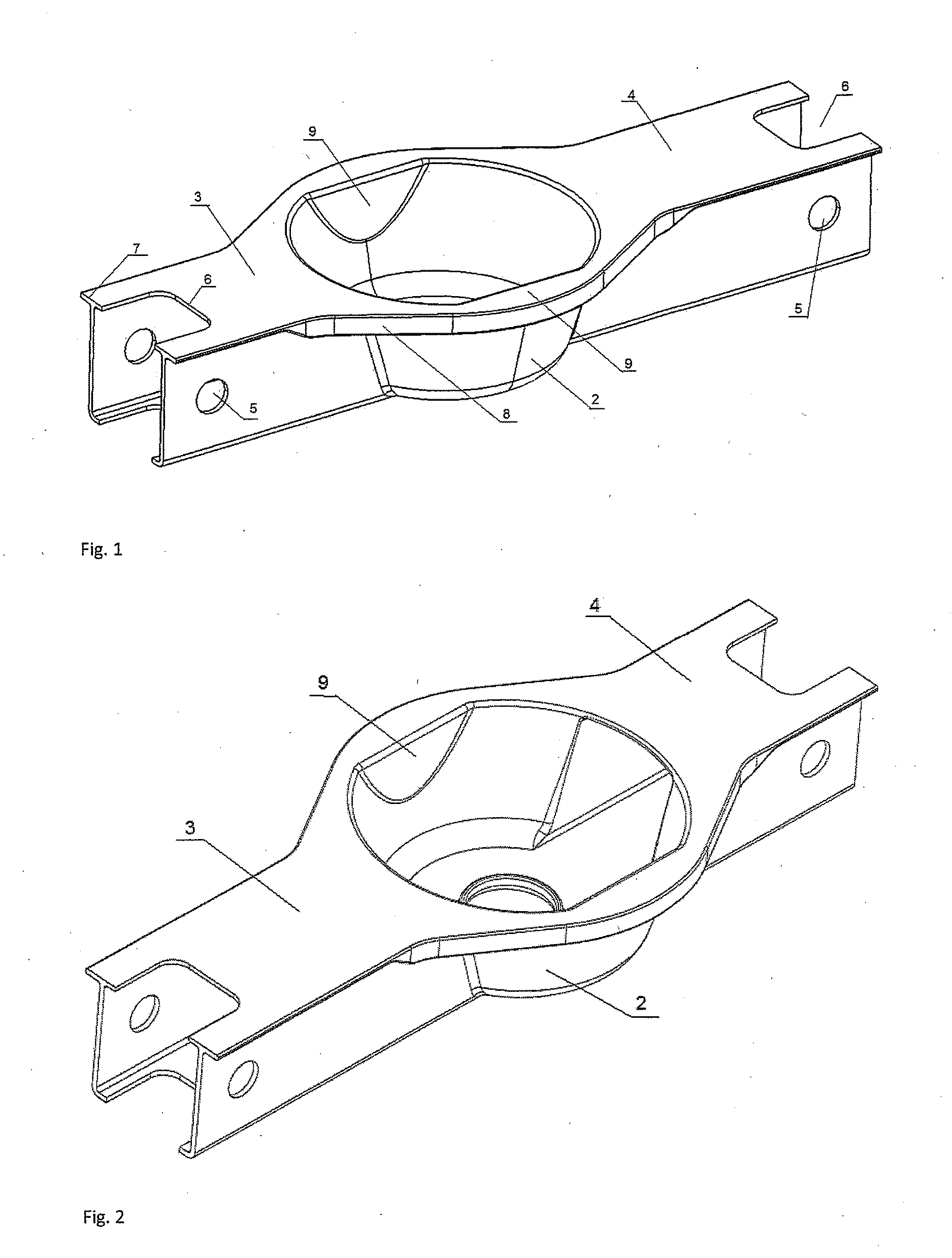
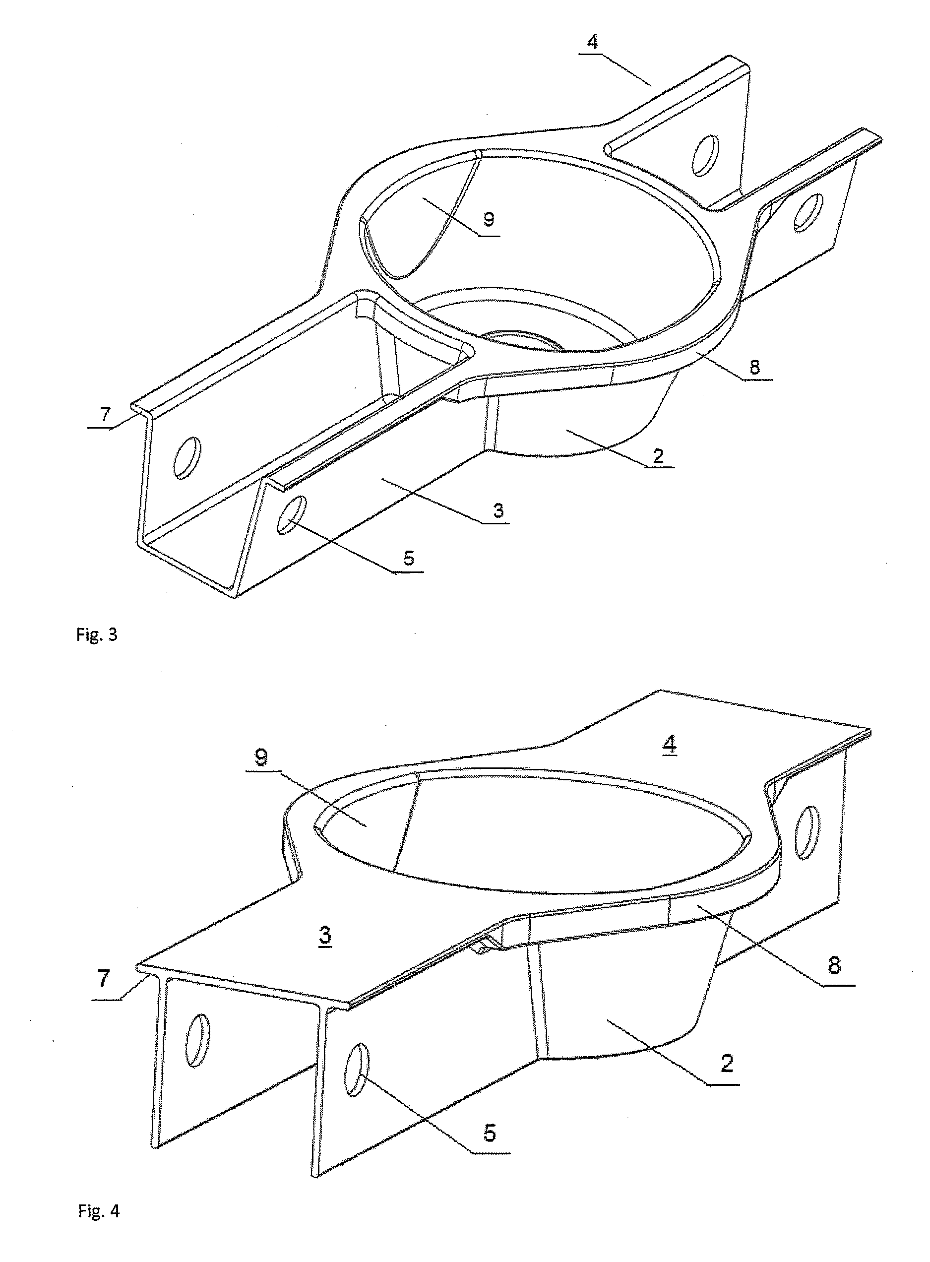
[0016]FIG. 1 shows a control arm 1 according to the invention. The control arm 1 includes a centrally located cup 2 forming a spring seat. On each side of the cup 2 there are branches 3, 4 projecting from the cup.

[0017]The branches 3, 4 may be located in line or with a small angle between the branches, sideways, vertically or both, and with the lower surfaces of the branches and spring seat meeting at the same level, i.e. with the spring seat recessed into the compound arm. In the distant ends of the branches there are made fastening holes 5 and cut-outs 6 for the mounting of the arm in the car. The branches are designed as closed channels. The channels may be square in cross section, but other shapes are also possible, such as rectangular or trapezoid. Flanges 7 are protruding along the upper part of the arm, on both sides thereof. The flanges are thickened in an area 8 around the seat 2. On the inside of the seat cup there are also thickened areas or wedges 9 on each side. The obj...


PUM

PropertyMeasurementUnit
Thicknessaaaaaaaaaa
Areaaaaaaaaaaa
Levelaaaaaaaaaa

Abstract

A control arm for the rear wheel suspension of a car where the control arm includes a cup-shaped spring mount with branches projecting from the spring seat. The branches may be designed as closed channels or U-shaped channels. In the upper part of the control arm there are flanges projecting from each side thereof. The flanges include a reinforced area around the spring seat. The cup-shaped spring seat is reinforces with wedges on the inside thereof. The spring seat and branches form a stiff frame structure. Also described is a method for manufacturing the control arm by forging.

Description

TECHNICAL FIELD[0001]The present invention relates to a control arm in the rear wheel suspension in a car, and in particular an elongate rear control arm which is the lower member in a multi-link rear wheel suspension, and more particular a lower arm carrying a spring or spring-and-damper unit.BACKGROUND ART[0002]From prior art, there are known several methods for producing such arms. A first method involves pressing two parts in sheet steel and joining the two parts along the rims. A recessed spring seat is formed in the lower part, with an opening in the upper part above the seat. The recessed mounting of the spring has the advantage that the spring will not protrude so far into the car body, i.e. the upper mounting point can be lowered giving more available room in the luggage compartment. Alternatively, a longer spring may be used allowing a longer stroke and a more comfortable ride. However, these steel arms are relatively heavy, even though being hollow. Generally, the un-spru...

Claims


Application Information

Patent Timeline
IPC IPC(8): B60G7/00B22D25/02B21D53/88B33Y10/00B33Y80/00
CPCB60G7/001B33Y10/00B33Y80/00B21D53/88B22D25/02B60G2206/10B60G2204/1244B60G2206/8103B60G2206/8101B60G2206/8112B60G2206/7102B21J9/027B21K7/00B60G7/00
Inventor PAULSEN, FRODE
Owner RAUFOSS TECH AS
Why Eureka
Try Eureka