Injector nozzle configuration for swirl Anti-icing system

a technology of anti-icing system and injector nozzle, which is applied in the direction of efficient propulsion technology, machines/engines, propellers, etc., can solve the problems of aircraft wings, aircraft loss, aircraft much more difficult to fly,

Active Publication Date: 2017-03-02
ROHR INC
View PDF53 Cites 28 Cited by
  • Summary
  • Abstract
  • Description
  • Claims
  • Application Information

AI Technical Summary

Benefits of technology

[0023]FIG. 9 shows the preferred / optimal area Injector area ratio distribution vs Injection nozzle station;

Problems solved by technology

The formation of ice on aircraft wings, tail fins, flight control surfaces, propellers, air inlets of engines, etc., has been a problem since the earliest days of heavier-than-air flight.
Any accumulated ice adds considerable weight, and changes the airfoil or inlet configuration thereby making the aircraft much more difficult to fly and, in some cases, has caused loss of aircraft.
In the case of gas turbine aircraft, large pieces of ice breaking loose from the leading edge of the gas turbine engine inlet housing can severely damage rotating fan-, compressor-, and turbine blades which extend across the flow path and interact with the working fluid or other internal fixed engine components (i.e. stator vanes) and cause engine failure.
These systems, however tend to be heavy and complex and remove only existing ice, rather than prevent ice formation.
While each of these methods may have some advantages none had been truly effective.
While often useful, these systems are not fully effective due to the complexity of the hot gas duct system.
While some heat effectiveness was achieved by the double skin design it was at the expense of high manufacturing cost and weight penalty, associated with the required chem-milling process to produce the inner skin and to provide the spray tube arrangement.

Method used


Image

  • Injector nozzle configuration for swirl Anti-icing system
  • Injector nozzle configuration for swirl Anti-icing system
  • Injector nozzle configuration for swirl Anti-icing system

Examples


Embodiment Construction

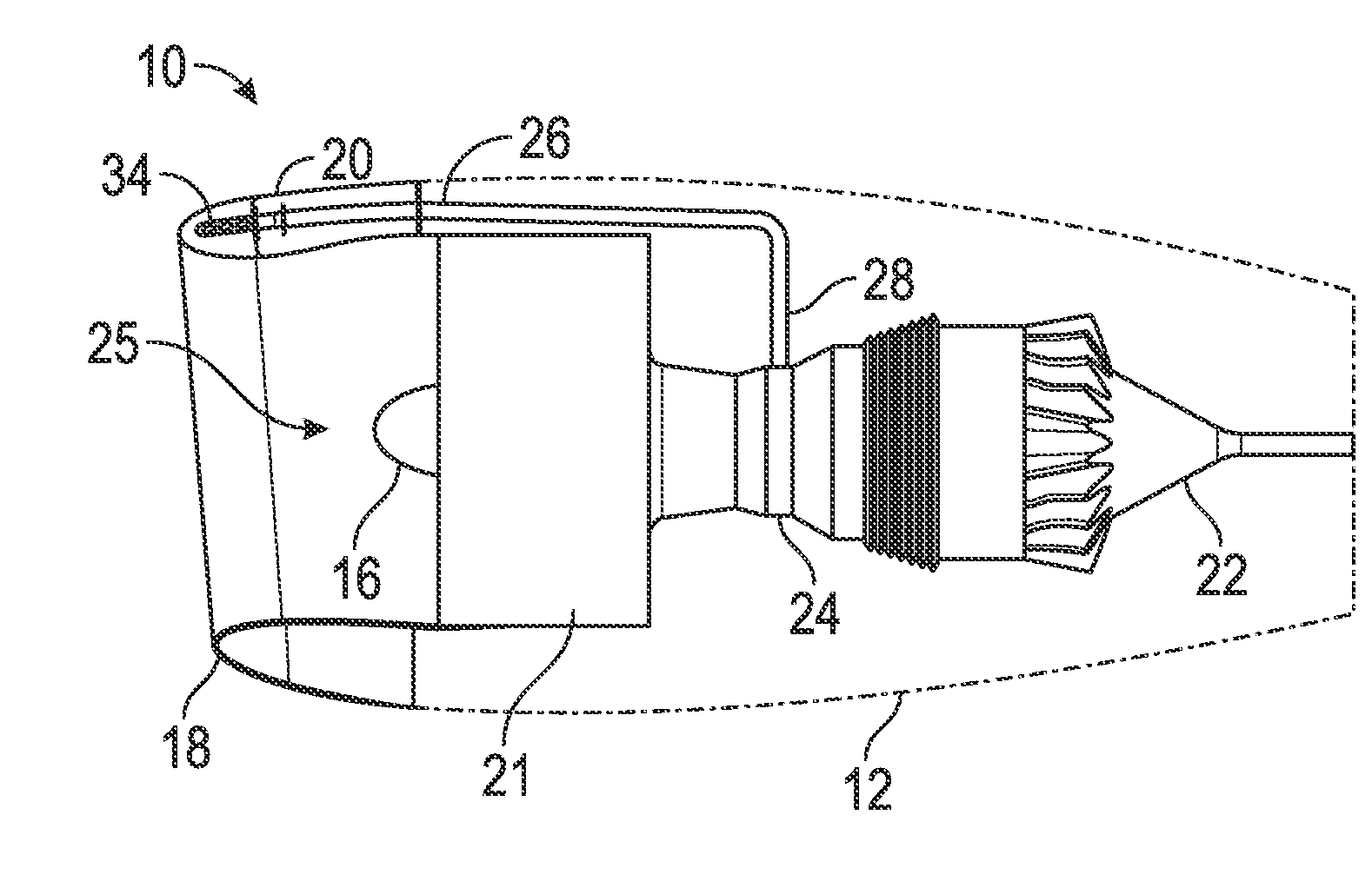
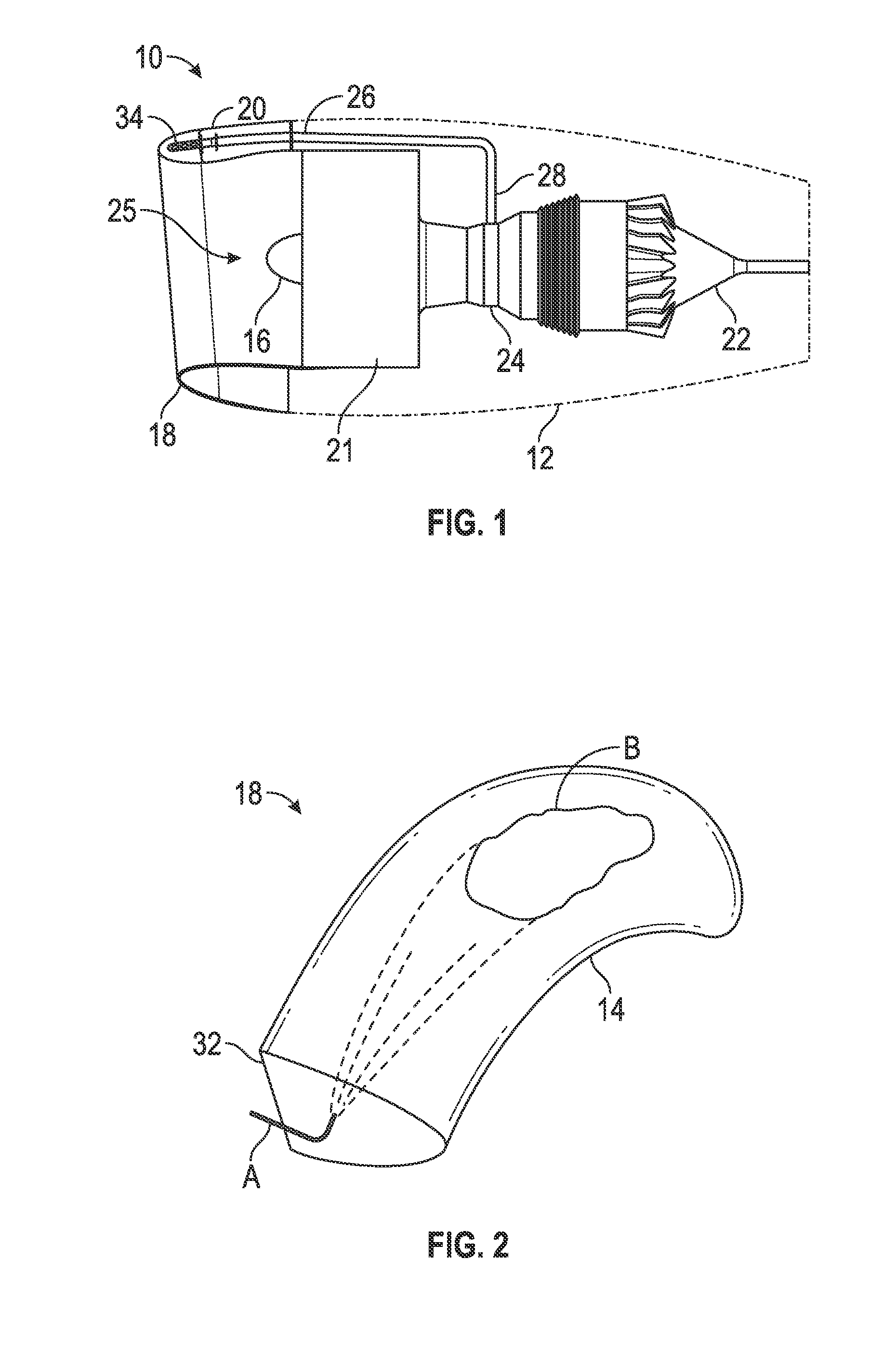
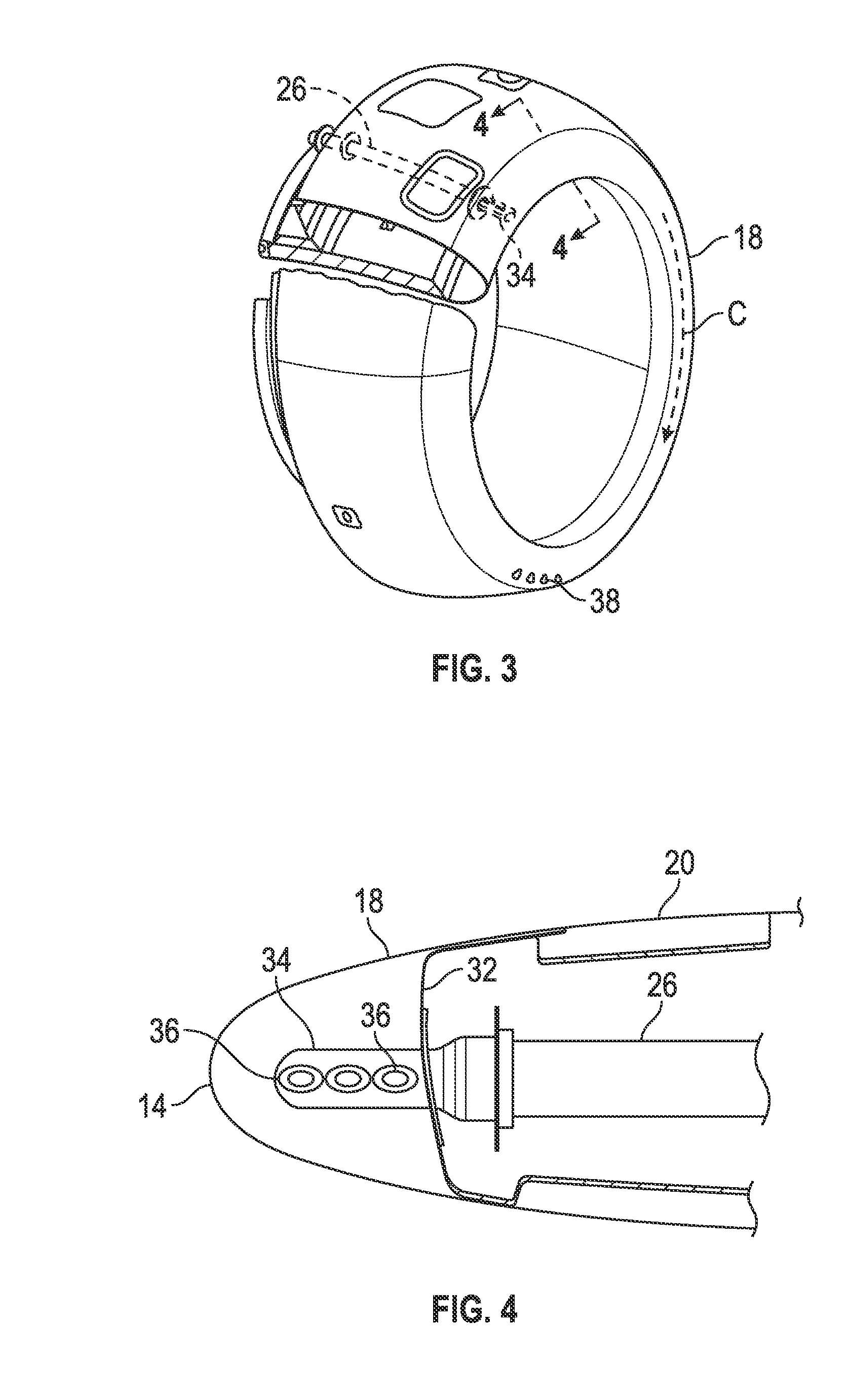
[0026]Referring now to the drawings in detail and in particular to FIG. 1, there is seen a schematic representation of an exemplary gas turbine engine 10 of the type suitable for aircraft propulsion. The gas turbine engine 10 is housed within a nacelle cowl housing 12. Air enters the gas turbine engine 10 through an air inlet section 25, between the nose cap 16 (or “spinner”) of the engine and the nose lip 18 or annular single skin housing which constitutes the forward most section of the gas turbine engine inlet housing 20 of the engine nacelle, some of which components have been omitted from FIG. 1 for purposes of ease of understanding. Engine thrust is produced by: (i) burning incoming core air flow and fuel within the engine 10 positioned with the central housing 24 and (ii) by compressing and passing the large mass bypass air flow of inlet air through the fan portion 21 of the gas turbine engine. Hot, high-pressure propulsion gases of the engine 10 pass through exhaust outlet 2...


PUM


Abstract

An anti-icing system for annular gas turbine engine inlet housings includes a substantially closed annular housing at a leading edge of the gas turbine engine inlet housing, the annular housing containing a quantity of air and a conduit extending from a source of high-pressure hot bleed air to the annular housing. The system also includes an injector connected to the end of the conduit and extending into the annular housing and one or more nozzles extending outwardly from the injector in a direction that the quantity of air circulates in the annular housing. The system may include one or both of an airfoil on an upstream side of the injector and an air direction element disposed one the injector that causes the quantity of air to be directed toward an outlet of the one or more nozzles.

Description

BACKGROUND OF THE INVENTION[0001]Embodiments of the present disclosure relate to anti-icing systems for aircraft jet engine (i.e. gas turbine) propulsion systems and more particularly, to nozzle configurations on an injector in a swirling rotational anti-icing system for an inlet of a gas turbine engine.[0002]Safety is a primary concern in the design or power propulsion systems for aircraft applications. The formation of ice on aircraft wings, tail fins, flight control surfaces, propellers, air inlets of engines, etc., has been a problem since the earliest days of heavier-than-air flight. Any accumulated ice adds considerable weight, and changes the airfoil or inlet configuration thereby making the aircraft much more difficult to fly and, in some cases, has caused loss of aircraft. In the case of gas turbine aircraft, large pieces of ice breaking loose from the leading edge of the gas turbine engine inlet housing can severely damage rotating fan-, compressor-, and turbine blades whi...

Claims


Application Information

Patent Timeline
Patent Type & Authority Applications(United States)
IPC IPC(8): F02C7/047B64D15/04
CPCF02C7/047F05D2260/201B64D15/04B64D33/02B64D2033/0233F01D25/02F05D2260/2212Y02T50/60B64D15/00F02C6/08F02C9/18
Inventor FRANK, JOEL H.RIBAROV, LUBOMIR A.
Owner ROHR INC
Why Eureka
Try Eureka