
Detection of and responses to time delays in networked control systems

Active Publication Date: 2017-03-02
FLORIDA INTERNATIONAL UNIVERSITY
View PDF6 Cites 16 Cited by
  • Summary
  • Abstract
  • Description
  • Claims
  • Application Information

AI Technical Summary

Benefits of technology

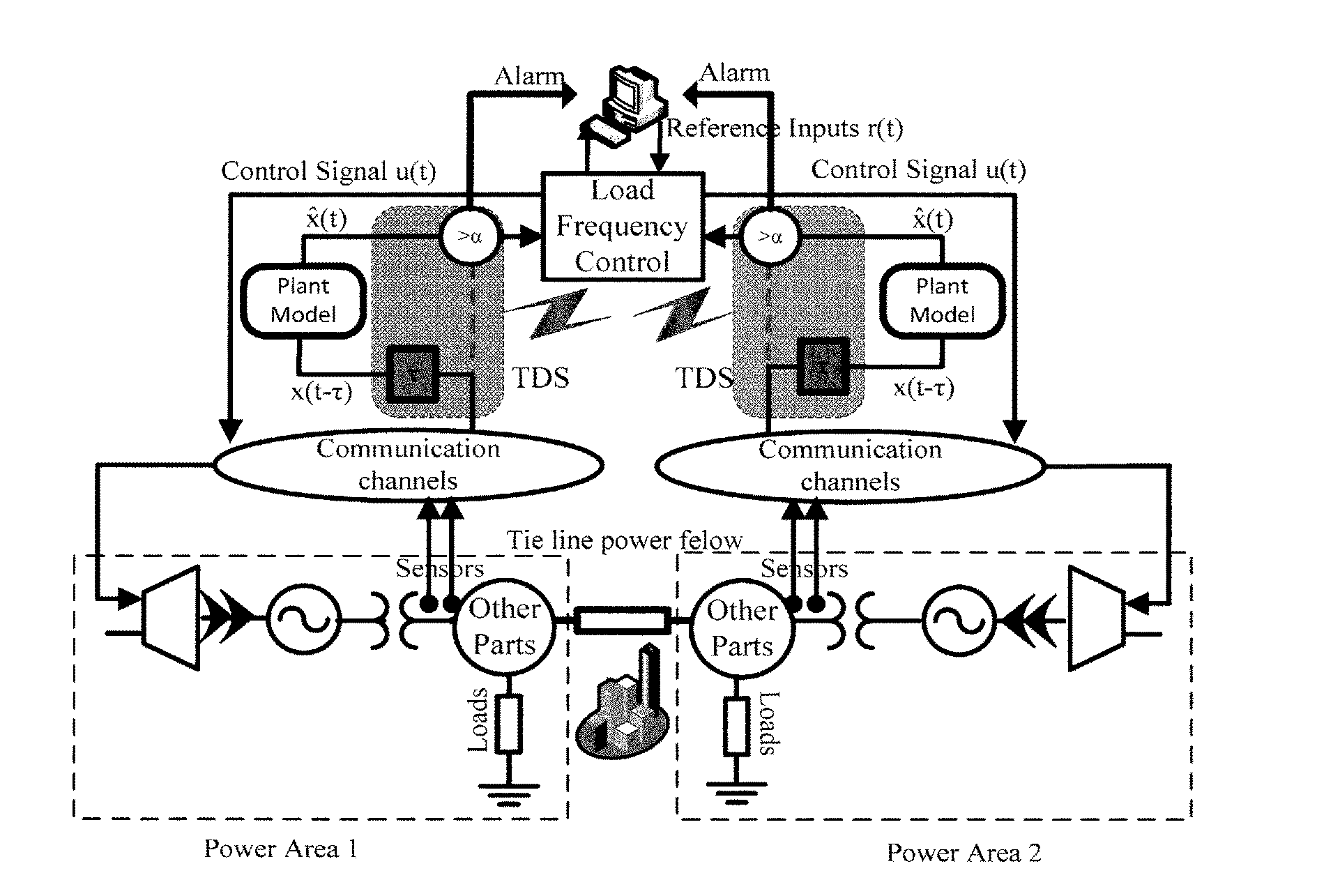
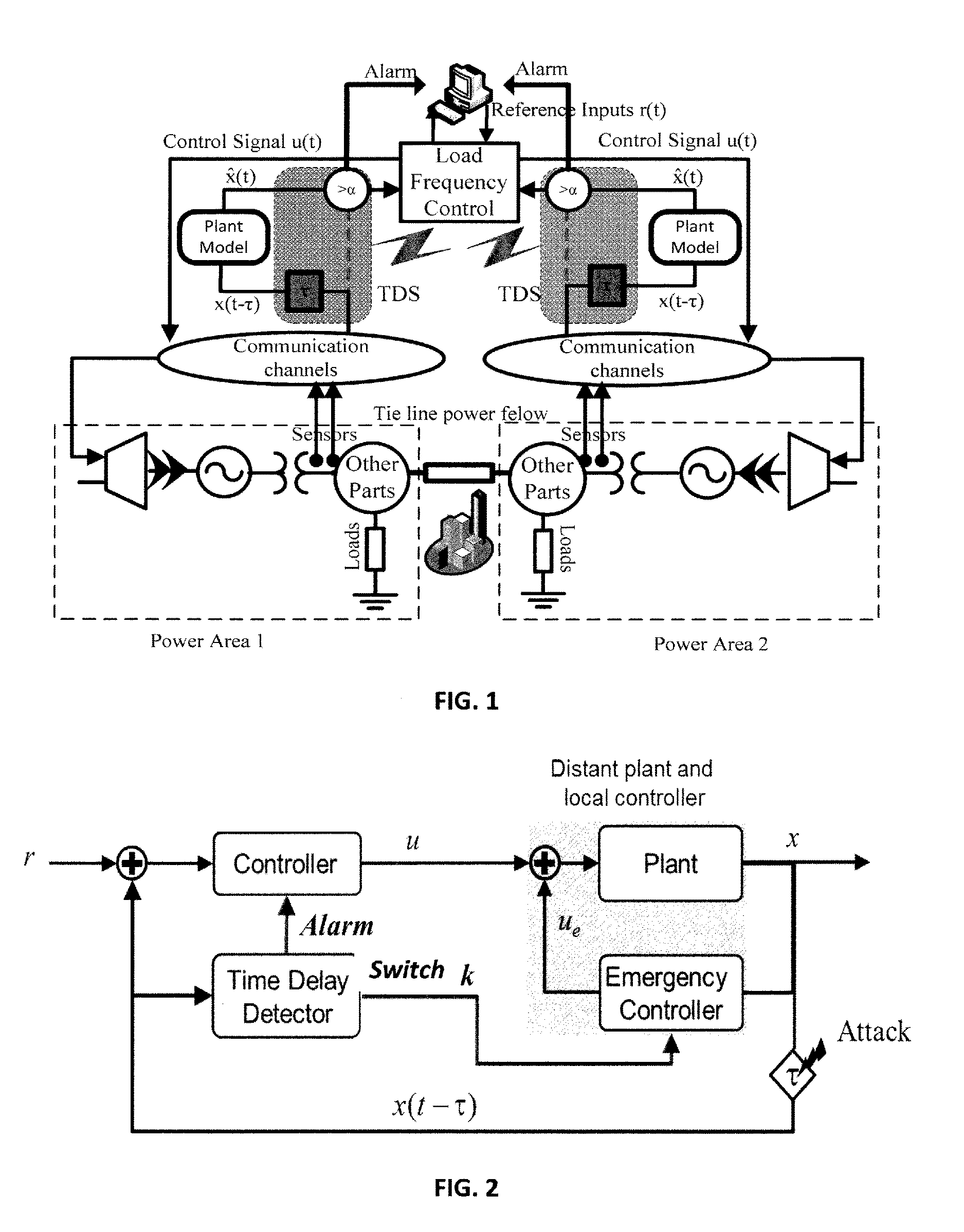
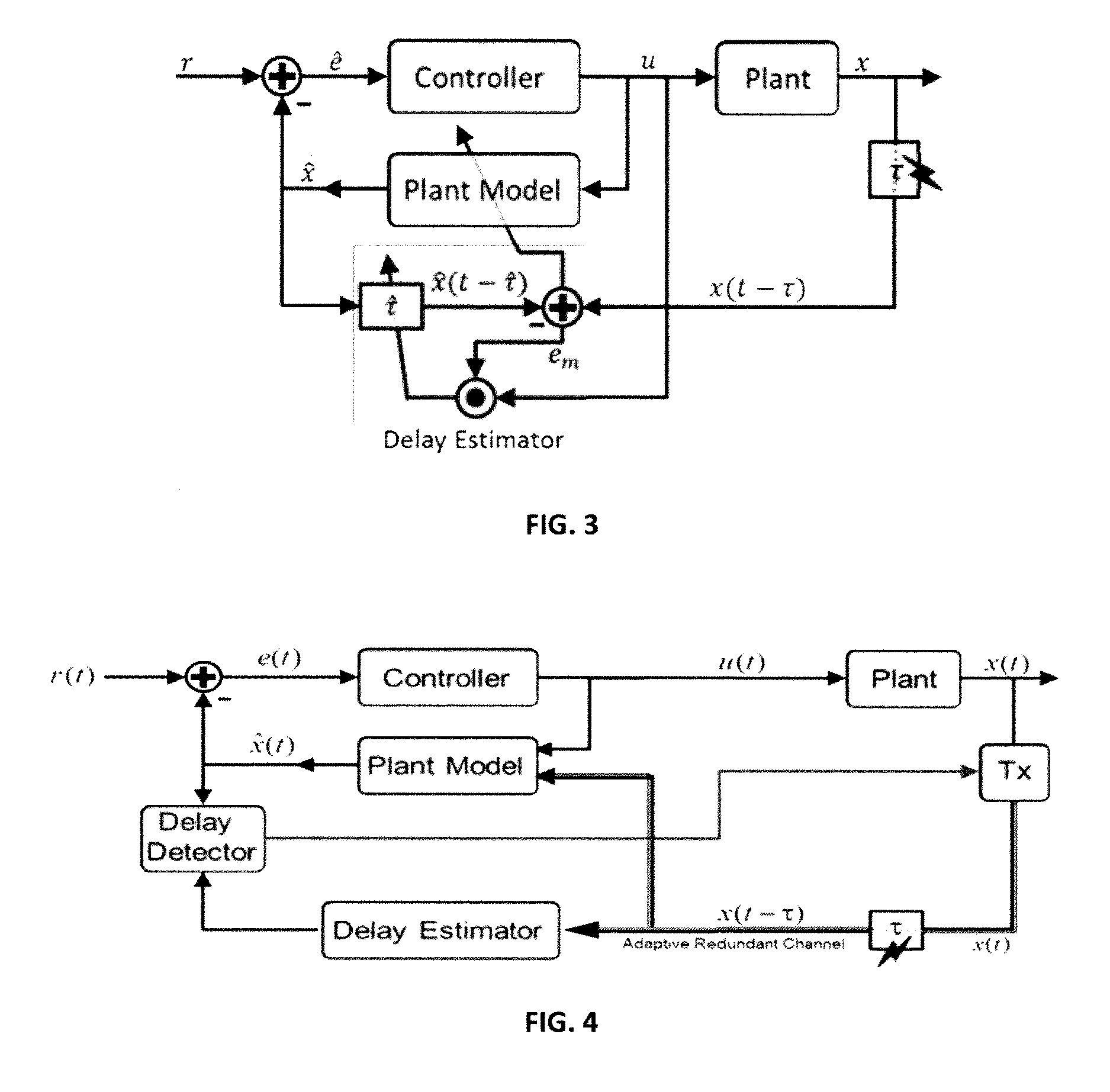
The patent text describes techniques and systems for detecting and addressing time delays in a control system for a plant or environment. The invention allows for quicker detection and analysis of time delays, and provides adaptable control capabilities to address the impact of time delays on the system's performance. This can include sending a control instruction to a local or emergency controller, or adjusting / adapting the control signal to compensate for the time delay. The invention also includes the ability to transmit subsequent communications packets over multiple redundant channels. Overall, the invention improves the efficiency and resilience of control systems in various industrial environments.

Problems solved by technology

Communications between the device and the controller (both sensing and control communications) are sometimes delayed as a result of the nature of the communications network (e.g., the network uses a slower transmission medium), problems or technical difficulties in the network (e.g., router failure), or the activities of an attacker intentionally attempting to degrade the performance of the network.
Time delays in the sensing and control communications can impact the stability of a system and degrade its performance, for example, when sensor telemetry messages from the device arrive with such a significant delay that it is difficult for the controller to appropriately react and adjust the operations of the device.
In power systems, these types of time delays exist in the sensing and control loops.
Nevertheless, time delays are present in PMUs measurements as a result of natural transmission lines [D. Dotta, A. S. Silva and I. C. Decker, “Wide-area measurements-based two-level control design considering signal transmission delay”, IEEE Trans. on Power Systems, vol.
Furthermore, modern power grids rely on computers and multi-purpose networks, making them vulnerable to cyber-attacks that can cause a major threat to life and economic productivity.

Method used


Image

  • Detection of and responses to time delays in networked control systems
  • Detection of and responses to time delays in networked control systems
  • Detection of and responses to time delays in networked control systems

Examples


example 1

[0111]In this simulation, the total simulation time is 50 seconds and the sampling time is 0.01 s. Assume that an adversary performs a TDS attack on feedback lines of both power areas. In the simulation, an attacker starts a TDS attack on the second power area (third state) at time 1 second for td3=5 s and then increases it to td3=10 s at 20 seconds. Furthermore, the adversary starts to attack the first power area (third state), at 1 second with td8=3 s and increased it to td8=4.5 s at 30 seconds. FIG. 5A shows TDS attack detection and tracking for the third state of the first power area. FIG. 5B shows TDS attack detection and tracking for the third state of the second power area.

[0112]FIGS. 5A and 5B show that the detection method could follow the time delay attack accurately. The stability value is set to τstable=0.4 s, based on stability analysis of an LFC system in Sargolzaei, Yen, and Abdelghani (“Time-Delay Switch Attack on Load Frequency Control in Smart Grid”, Publication in...

example 2

[0114]Examples 2-3 show simulations with embodiments including an adaptive controller. Example 2 uses a simple single-input, single-output system under a variable time delay attack with a variable reference signal. This test demonstrates the usability and efficiency of the techniques and systems. The simulation model is given by

x.(t)=-0.7x(t)+2u(t)r(t)={1--γ2tt≤Ta4-γ1(t-Tb)(sin(2πωat)+1)otherwiseτ(t)=T1-λ1t(sin(2πω1t)+1)+T2(1--λ2t)+1(54)

where the total simulation time T=500 sec., Ta=T / 2, Tb=T / 2.2, T1=T2=T / 10, λ1=0.005, λ2=0.0005, γ1=0.07, γ2=0.004, ωa=0.06, ωl=0.005 and the sampling time is 0.01 sec.

[0115]A proposed PID controller tracks the reference signal under TDS attack. FIG. 6A shows the tracking performance of a single-input, single-output system under TDS attack. FIG. 6A indicates the state of the plant given in the Equation (54) and tracking the desired trajectory r(t). The tracking is almost perfect, even though the time delay is varying by τ(t).

[0116]FIG. 6B shows the TDS...

example 3

[0117]Having shown that the simple, modified model-based control and time-delay estimation techniques and systems work for simple single-input, single-output systems under variable time delay attack, distributed power control systems where time delay mitigation strategies are paramount are now considered.

[0118]In an LFC system where the controller's job is to regulate the states of a network of power plants, analysis begins with the design of an optimal controller for the LFC in normal operation (e.g., with no attack). Consider a two state power plant model with the performance index described by

J=12∫0tf{XT(t)QX(t)+UT(t)RU(t)}t(55)

where matrix QεRn×n is positive semi-definite and RεRm×m is positive definite. The optimal control problem is to obtain optimal control U*(t) that minimizes the performance index in Equation (55), subject to the dynamic of the system with no time-delay in its states.

[0119]Simulation studies have been conducted to evaluate the effects of TDS attacks on the ...


PUM


Abstract

To ameliorate the detrimental effects of time delays, techniques and systems are disclosed for detecting time delays in a plant, facility, or environment (such as a power system) controlled by an NCS, and for providing more resilient control capabilities for adapting to the detected time delays. A time delay estimate can be determined by comparing the expected state of the plant, calculated from a plant model, with the state of the plant described by its telemetry data. Techniques for adapting to a time delay include: switching to an emergency controller and acting in accordance with a local reference model; sending adjusted control commands in accordance with an expected plant state; and instructing a transmitter to transmit subsequent communications packets over multiple redundant communication channels.

Description

BACKGROUND[0001]Time delays are ubiquitous in nature. They occur in a wide variety of natural and man-made control systems. In an environment with a networked control system (NCS), a physical or virtual device may provide sensor feedback to a controller, which in turn controls the output or operation of the devices via control instructions. Both types of communications may be sent over a communications network. Communications between the device and the controller (both sensing and control communications) are sometimes delayed as a result of the nature of the communications network (e.g., the network uses a slower transmission medium), problems or technical difficulties in the network (e.g., router failure), or the activities of an attacker intentionally attempting to degrade the performance of the network.[0002]Time delays in the sensing and control communications can impact the stability of a system and degrade its performance, for example, when sensor telemetry messages from the d...

Claims


Application Information

Patent Timeline
IPC IPC(8): G05B13/02
CPCG05B13/021G05B13/047G05B2219/25404G05B2219/34413
Inventor SARGOLZAEI, ARMANABDELGHANI, MOHAMEDYEN, KANG K.
Owner FLORIDA INTERNATIONAL UNIVERSITY
Learn More