Method for detecting floor obstacle using laser range finder

Active Publication Date: 2017-03-02
KOREA UNIV RES & BUSINESS FOUND
View PDF2 Cites 17 Cited by
  • Summary
  • Abstract
  • Description
  • Claims
  • Application Information

AI Technical Summary

Benefits of technology

[0028]According to the above features of the present invention, an obstacle including a relatively small floor obstacle existing on the driving path of a mobile robot can be detected more effectively using a laser range finder, thereby more stably acq

Problems solved by technology

However, in case of using a 2D laser range finder, each grid cell has few distance information and thus, it is difficult to analyze data.
Also, the size of the obstacle which can be detectable is limited due to the gird resolution.
Meanwhile, the detection range is limited in the indoor environment.
In case of a 3D laser range finder having wide detection range, it is difficult to detect a terrain near the mobile robot.
It is also difficult to add an addition 3D range finder for observing only the terrain near the mobile robot due to a high price.
However, it is disadvantageous that the classification of the driving surface from the plurality of features depends on Heuristic threshold and thus, problematically, Heuristic constant must be redefined with respect to a certain environment or platform.
Since the above mentio

Method used


Image

  • Method for detecting floor obstacle using laser range finder
  • Method for detecting floor obstacle using laser range finder
  • Method for detecting floor obstacle using laser range finder

Examples


Embodiment Construction

[0038]Hereinafter, embodiments according to the invention will be explained in detail referring to the attached drawings.

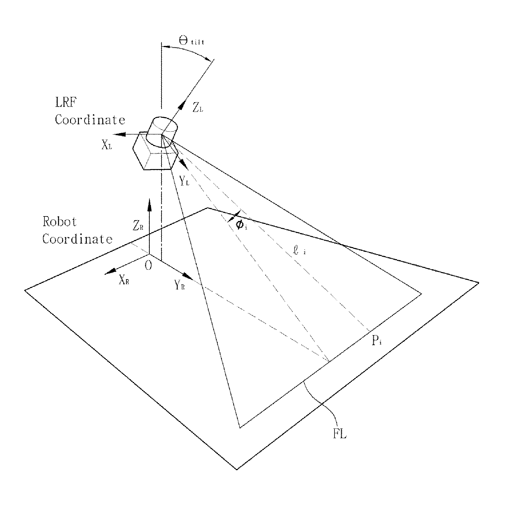
[0039]FIG. 1 shows a coordinate frame structure of a mobile robot and a laser range finder according to the present invention. In an example of the present invention, 2D laser range finder is used as the laser range finder and the distance is determined by detecting a laser which is incident forwardly at a predetermined angle and then is reflected back.

[0040]Referring to FIG. 1, the laser range finder is installed on the mobile robot at an inclination angle θtilt to a floor. An ith measurement point pi of the laser range finder has sensing values of a distance li from the laser range finder and an angle φi.

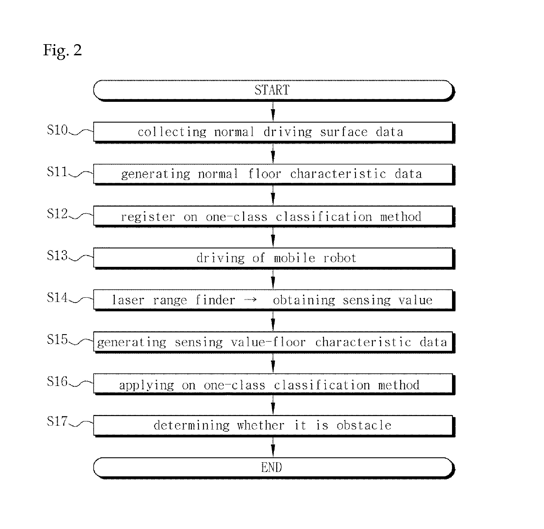
[0041]FIG. 2 shows a method of detecting a floor obstacle using a laser range finder according to the present invention.

[0042]First, normal floor characteristics data with regard to a flat normal driving surface having no floor obstacles is generated (S11). In a...


PUM


Abstract

The invention relates to a method of detecting a floor obstacle using a laser range finder comprising the following steps: (a) generating normal floor characteristic data with regard to a flat normal driving surface having no floor obstacle; (b) registering the normal floor characteristic data on a pre-registered one-class classification method; (c) obtaining sensing value of the laser range finder according to the driving of a mobile robot; (d) generating sensing value-floor characteristic data with respect to the sensing value; and (e) determining whether the sensing value indicates a normal driving surface or a floor obstacle by applying the sensing value-floor characteristic data to the one-class classification method. Therefore, an obstacle including a relatively small floor obstacle existing on the driving path of a mobile robot can be detected more effectively using a laser range finder, thereby providing more stably an area where the mobile robot can travel.

Description

CROSS-REFERENCE TO RELATED APPLICATIONS[0001]This application claims the benefit under 35 USC §119(a) of Korean Patent Application No. 10-2015-0122424 filed on Aug. 31, 2015 in the Korean Intellectual Property Office, the entire disclosure of which is incorporated herein by reference for all purposes.BACKGROUND[0002]1. Field[0003]The invention relates to a method of detecting a floor obstacle using a laser range finder and in particular, to a method of detecting a relatively small floor obstacle existing on the driving path of a mobile robot using a laser range finder.[0004]2. Description of Related Art[0005]The combination of autonomous driving of a mobile robot to service filed is being studied. Under the environments, the classification of an area where the mobile robot from given environments can drive must be carried out preferentially for the safe driving of the mobile robot. An ability to detect the drivable area influences the safety of the robot as well as the driving perfo...

Claims


Application Information

Patent Timeline
IPC IPC(8): G05D1/02G01V8/12B60W30/095G01S17/931
CPCG05D1/024B60W30/0956Y10S901/01B60W2420/62G01V8/12G01C7/04G01S17/42G01S7/4802G01S17/931
Inventor CHUNG, WOOJINLEE, HYUNSUK
Owner KOREA UNIV RES & BUSINESS FOUND
Why Eureka
Try Eureka