System And Method For Visibility Enhancement

a technology of visibility enhancement and system, applied in image enhancement, television systems, instruments, etc., can solve the problems of high cost and complicated prior art assistant systems, and achieve the effect of increasing the contrast of that part, and reducing the cost of the system

Active Publication Date: 2017-03-02
SMR PATENTS S A R L
View PDF11 Cites 6 Cited by
  • Summary
  • Abstract
  • Description
  • Claims
  • Application Information

AI Technical Summary

Benefits of technology

[0017]In another example, altering the contrast of that part of the image that shows the at least one object comprises increasing the contrast. Advantageously, by increasing the contrast of that part of the image that shows the at least one object increases the visibility of the at least one object that is displayed to the driver by means of the display means.
[0018]In yet another example, the image processing means is further adapted to manipulate the at least one image to generate a manipulated image by altering the contrast of that part of the image that does not show the at least one object. For example, the contrast of that part of the image that does not show the at least one object can be decreased so that the attention of the driver is drawn away from the surroundings of that at least one object. However, alternatively, depending on the size of that at least one object, for example, in case the at least one object is very small compared to its surroundings, the contrast of the part of the image that does not show the at least one object can be increased while the contrast of the object is decreased. Advantageously, by using the later scheme, the presence of a very small object can be better indicated to the driver.

Problems solved by technology
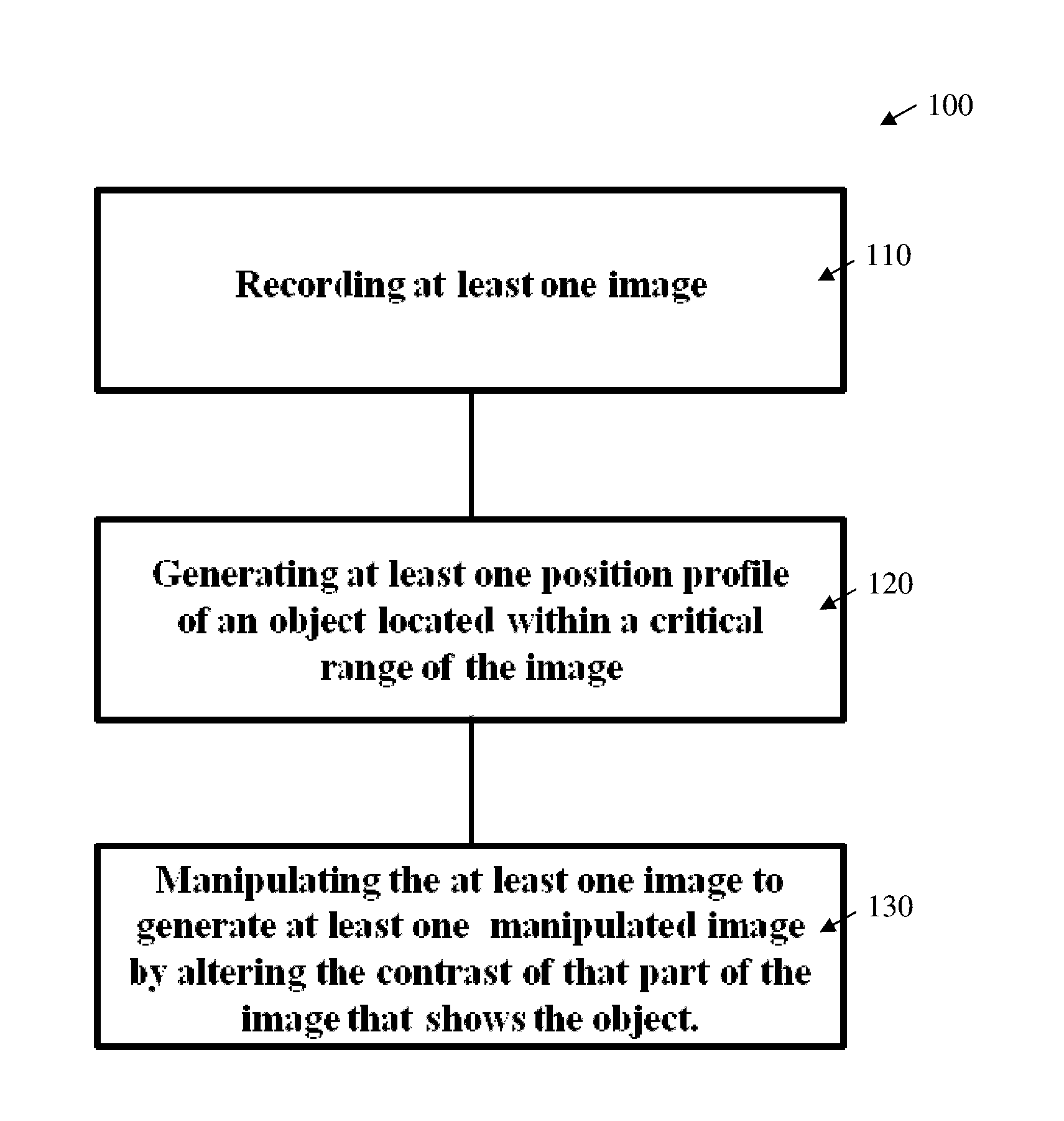
Most of these prior art assistant systems, however, are highly complicated, expensive, only capture the scene in front of the car, and employ confusing highlighting schemes where in the regions of the image with no objects the noise is increased which results in unpleasant results.

Method used


Image

  • System And Method For Visibility Enhancement
  • System And Method For Visibility Enhancement
  • System And Method For Visibility Enhancement

Examples


Embodiment Construction

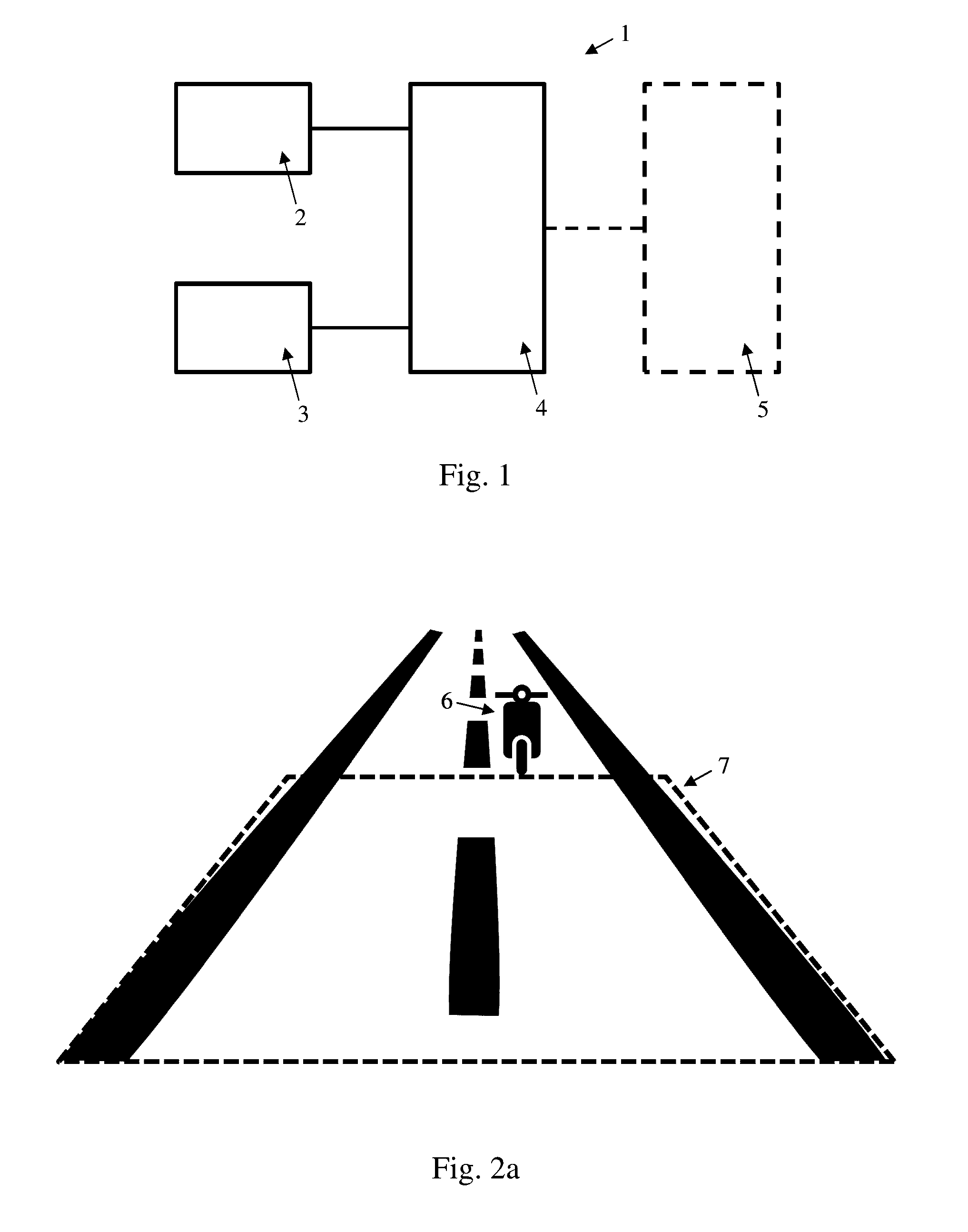
[0036]Referring now to the drawings, there is illustrated in FIG. 1 a system 1 for visibility enhancement according to an embodiment of the invention. The system 1 comprises first sensor means 2 that comprises a camera, second sensor means 3 and image processing means 4.

[0037]The camera comprised within the first sensor means 2 could be a digital camera that is installed on or in the housing of a rear view equipment of a motor vehicle. The second sensor means 3 could be at least one infrared sensor, laser sensor, and / or radar sensor. However, the skilled person would know that the second sensor means 3 could be also composed of more than one, and / or of different sensors. The second sensor means 3 has essentially the job of detecting areas in the image that have objects closer than a certain distance using state of the art object detection techniques.

[0038]In the example that is shown in FIG. 1, both sensor means 2 and 3 are shown as separate entities. However, the skilled person wou...


PUM


Abstract

A system for visibility enhancement comprises a first sensor means comprising a camera adapted to record at least one image. A second sensor means is adapted to generate at least one position profile of at least one object located within a critical range of the first sensor means. An image processing means is adapted to receive a first input signal from the first sensor means containing the at least one image and a second input signal from the second sensor means containing the at least one position profile of the at least one object located within the critical range. The image processing means further manipulates the at least one image to generate a manipulated image by altering the contrast of that part of the image that shows the at least one object located within the critical range. A corresponding method of visibility enhancement is also disclosed.

Description

CROSS-REFERENCE TO RELATED APPLICATIONS[0001]This application claims priority from European Patent Application No. 15183520.4, filed Sep. 2, 2015, the disclosure of which is incorporated herein by reference.BACKGROUND OF THE INVENTION[0002]This invention relates to a system and to a method for visibility enhancement. The system comprises first and second sensor means to obtain image information and position information with regards to the surroundings of a motor vehicle, and image processing means to manipulate image information.[0003]Modern day intelligent motor vehicle assistant systems use image data of cameras that are installed in various locations in or at the vehicle for warning the driver of hazardous situation. For example, these assistant systems can generate a cross traffic alert, or autonomously detect pedestrians. Most modern day assistant systems do not just process the image information to create an audible or optical warning, but also modify image data obtained from ...

Claims


Application Information

Patent Timeline
Patent Type & Authority Applications(United States)
IPC IPC(8): G06T5/00H04N5/225B60K35/00G06T7/00B60R1/00G06K9/00G06K9/20G01S13/931G06V10/147
CPCG06T5/008B60K2350/106H04N5/2252G06K9/209G06T7/0065G06T7/004B60R1/00B60K35/00G06T2207/10028G06T2207/20172G06T2207/30236G06T2207/30261G06T2207/20004B60R2300/8066G06K9/00805G01C11/06B60R2300/301B62D15/029G01S13/867G01S13/931G08G1/165G08G1/166B60R2300/307G06T2200/04G06T2207/10012G06T2207/10048G06T7/593G06T7/11G08G1/143G06T7/70G06T7/55G01S13/865B60K2370/152G06V20/58G06V10/147B60W2050/146B60W30/08H04N23/51
Inventor ALAHMAR, AHED
Owner SMR PATENTS S A R L
Why Eureka
Try Eureka