Immersion cooling system with low fluid loss

a cooling system and immersion technology, applied in indirect heat exchangers, lighting and heating apparatus, instruments, etc., can solve problems such as loss of working fluid

Active Publication Date: 2017-03-02
MIYOSHI MARK
View PDF34 Cites 73 Cited by
  • Summary
  • Abstract
  • Description
  • Claims
  • Application Information

AI Technical Summary

Benefits of technology

[0013]The vapor redirection structure can be configured to be at least partially submerged within the working fluid. The system can additionally include a float configured to overlie portions of the working fluid exposed to the secondary chamber to inhibit evaporation of working fluid into the secondary chamber. The primary condenser can include a filtration section near the top of the primary condenser, the filtration section comprising condenser components having narrower gas paths passing between them than the gas paths extending adjacent lower sections of the primary condenser.

Problems solved by technology

However, when the cooling system is opened to allow access to the electronic components within or for other system maintenance, some loss of working fluid will occur.

Method used


Image

  • Immersion cooling system with low fluid loss
  • Immersion cooling system with low fluid loss
  • Immersion cooling system with low fluid loss

Examples


Embodiment Construction

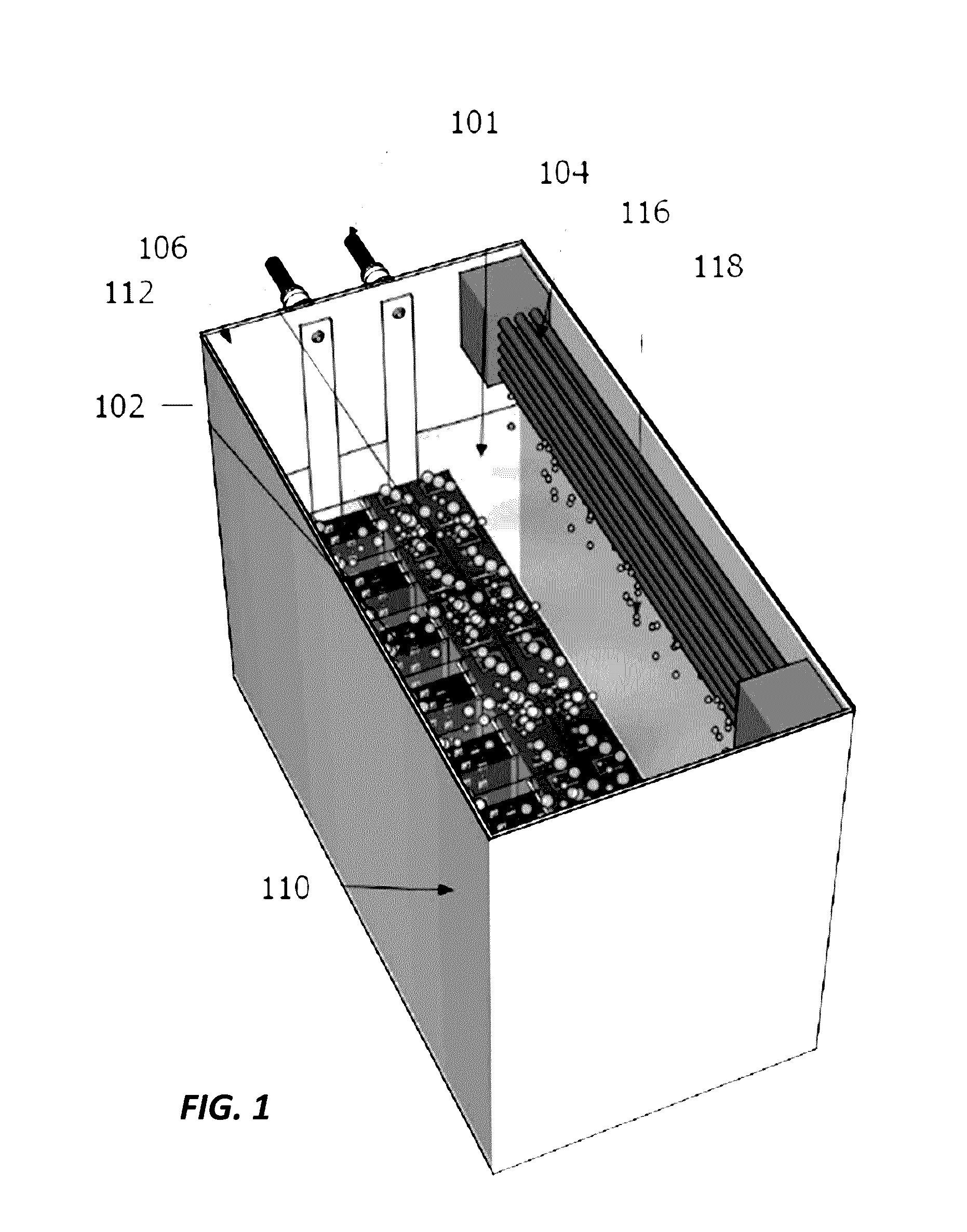
[0060]FIG. 1 is a perspective view of a two-phase immersion cooling (TPIC) system, also commonly referred to as a TPIC system or TPIC tank. The system 100 is configured to contain and cool heat-generating components (HGCs) 102 which are directly submerged in a dielectric working fluid (DWF) 104, contained within the basin of a container 110 having a lid 112. The HGC 102 may be any electrical components which generate a substantial amount of heat and which require or benefit from active cooling, such as computer processors, hard drives, or similar components. Power and other communication is supplied to the HGC 102 via the power 101.

[0061]The DWF 104 can be in direct or indirect contact with the HGC 102 to allow conductive heat transfer from the HGC to the DWF 104. In the case of indirect contact, a heat spreader, heatsink, porous heat transfer enhancing coating or other medium can be interposed between a portion of the HGC 102 and the DWF 104.

[0062]The DWF 104 can have a low boiling...


PUM


Abstract

Two-phase immersion cooling systems can be used to cool electronic components submerged within a dielectric working fluid, but are susceptible to costly losses of working fluid when the cooling systems are opened to allow access to the electronic components for service or replacement. By selectively sealing certain portions of the cooling systems, loss of vaporized working fluid can be reduced.

Description

CROSS-REFERENCE TO RELATED APPLICATIONS[0001]This application claims priority to U.S. Provisional Application No. 62 / 211,415, filed Aug. 28, 2015, entitled IMMERSION COOLING SYSTEM WITH LOW FLUID LOSS, the disclosure of which is hereby incorporated by reference in its entirety.BACKGROUND[0002]Technical Field[0003]This disclosure relates to two-phase immersion cooling systems.[0004]Description of the Related Art[0005]Two-phase immersion cooling systems can be used to cool electronics that generate enough heat to require an active cooling solution. When submerged in a working fluid, which can have a relatively low boiling point, heat absorbed by the fluid surrounding the electronic component can vaporize the fluid, carrying heat away from the electronic component. A condenser coil or similar structure overlying the tank can cause condensation of the vaporized working fluid, which can then be returned to the reservoir of working fluid surrounding the electronic component.[0006]However,...

Claims


Application Information

Patent Timeline
Patent Type & Authority Applications(United States)
IPC IPC(8): H05K7/20
CPCH05K7/203H05K7/2049H05K7/20381H05K7/20318H05K7/20809F28D15/0266F28F9/007G06F2200/201H01L21/67109H01L21/67184H01L23/32H01L23/34H01L23/40H01L23/4006H01L23/42H01L23/427H01L23/44H01L23/46H01L23/473
Inventor MIYOSHI, MARK
Owner MIYOSHI MARK
Why Eureka
Try Eureka