Systems, Devices, Components and Methods for Detecting the Locations of Sources of Cardiac Rhythm Disorders in a Patient's Heart

a technology of source location and cardiac rhythm, applied in the field of medicine, can solve the problems of inability to show the direction of af wavefront propagation, inability to show the topera system, and limited success rate of rf ablation in treating af cases

Active Publication Date: 2017-03-09
ABLACON INC
View PDF5 Cites 49 Cited by
  • Summary
  • Abstract
  • Description
  • Claims
  • Application Information

AI Technical Summary

Problems solved by technology

RF ablation success rates in treating AF cases are currently limited, however, by a lack of diagnostic tools that are capable of precisely determining the source (or type), and location, of such AF drivers.
In particular, the TOPERA system cannot show if a circular EGM wavefront is actively generated by a re-entry mechanism and is therefore is a driver of AF (i.e., an active rotor), or whether a circular EGM wavefront simply represents turbulence passively generated by an EGM wavefront hitting a barrier (i.e., a passive rotor).
In addition, the TOPERA system does not show the direction of AF wavefront propagation, and does not provide the spatial or temporal resolution required to detect singularities associated with the generation of an active rotor.
2016) reported that the results obtained using TOPERA FIRM technology were inferior to those provided by non-specific ablation of the posterior wall of the left atrium.
Moreover, the results suggested that FIRM based ablation is not sufficient for therapeutic success without pulmonary vein isolation (PVI) being performed in parallel.
Nanthakumar at the 2016 CardioStim Convention in Nice, France, however, this method remains incapable of dealing successfully with complex data sets, such as those obtained during an episode of AF.

Method used


Image

  • Systems, Devices, Components and Methods for Detecting the Locations of Sources of Cardiac Rhythm Disorders in a Patient's Heart
  • Systems, Devices, Components and Methods for Detecting the Locations of Sources of Cardiac Rhythm Disorders in a Patient's Heart
  • Systems, Devices, Components and Methods for Detecting the Locations of Sources of Cardiac Rhythm Disorders in a Patient's Heart

Examples


Embodiment Construction

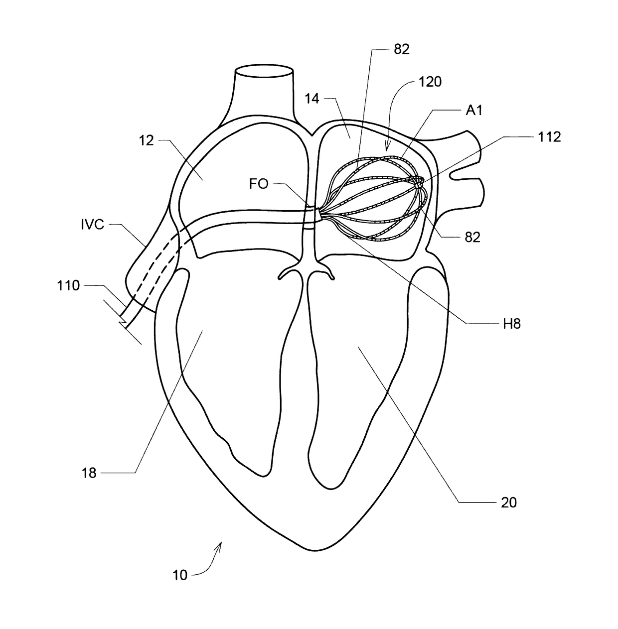
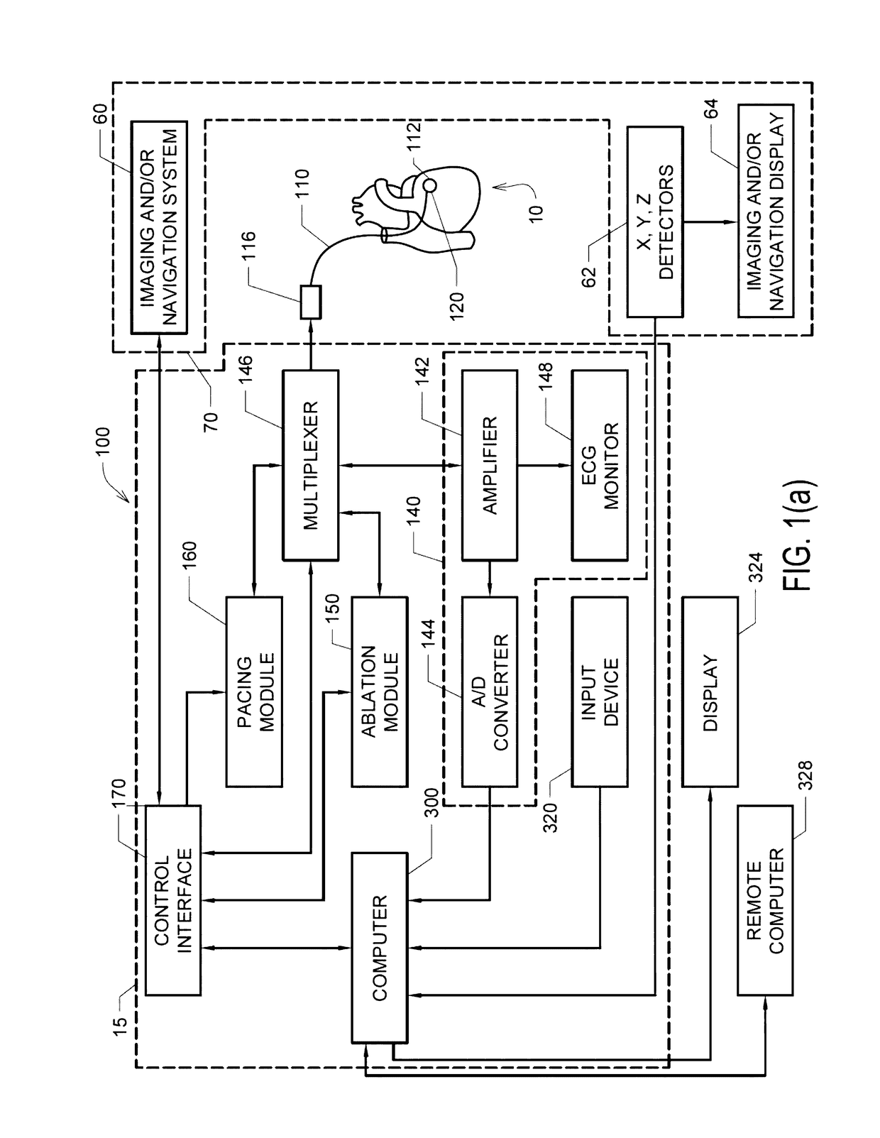
[0031]Described herein are various embodiments of systems, devices, components and methods for diagnosing and treating cardiac rhythm disorders in a patient's heart using electrophysiological mapping techniques, as well as imaging, navigation, cardiac ablation and other types of medical systems, devices, components, and methods. Various embodiments described and disclosed herein also relate to systems, devices, components and methods for discovering with enhanced precision the location(s) of the source(s) of different types of cardiac rhythm disorders and irregularities. Such cardiac rhythm disorders and irregularities, include, but are not limited to, arrhythmias, atrial fibrillation (AF or A-fib), atrial tachycardia, atrial flutter, paroxysmal fibrillation, paroxysmal flutter, persistent fibrillation, ventricular fibrillation (V-fib), ventricular tachycardia, atrial tachycardia (A-tach), ventricular tachycardia (V-tach), supraventricular tachycardia (SVT), paroxysmal supraventricu...


PUM


Abstract

Disclosed are various examples and embodiments of systems, devices, components and methods configured to detect a location of a source of at least one cardiac rhythm disorder in a patient's heart. In some embodiments, electrogram signals are acquired from inside a patient's heart, and subsequently normalized, adjusted and / or filtered, followed by generating a two-dimensional spatial map, grid or representation of the electrode positions, processing the amplitude-adjusted and filtered electrogram signals to generate a plurality of three-dimensional electrogram surfaces corresponding at least partially to the 2D map, one surface being generated for each or selected discrete times, and processing the plurality of three-dimensional electrogram surfaces through time to generate a velocity vector map corresponding at least partially to the 2D map. The resulting velocity vector map is configured to reveal the location of the source of the at least one cardiac rhythm disorder, which may be, by way of example, an active rotor in a patient's myocardium and atrium.

Description

RELATED APPLICATIONS[0001]This application claims priority and other benefits from Patent Application PCT / EP2015 / 001801 to Ruppersberg filed on Sep. 7, 2015, which is entitled “Elongated Medical Device Suitable for Intravascular Insertion and Method of Making an Elongated Medical Device Suitable for Intravascular Insertion” (hereafter “the '001801 patent application”). This application also claims priority and other benefits from Patent Application PCT / EP2015 / 001803 to Ruppersberg filed on Sep. 7, 2015, which is entitled “Elongated Medical Device Suitable for Intravascular Insertion and Method of Making an Elongated Medical Device Suitable for Intravascular Insertion” (hereafter the '001803 patent application”). The respective entireties of the '001801 and '001803 patent applications are hereby incorporated by reference herein.FIELD OF THE INVENTION[0002]Various embodiments described and disclosed herein relate to the field of medicine generally, and more particularly to diagnosing ...

Claims


Application Information

Patent Timeline
Patent Type & Authority Applications(United States)
IPC IPC(8): A61B5/04A61B18/14A61B5/0452A61B5/044A61B5/042A61B5/00A61B5/363A61B5/364
CPCA61B5/04017A61B5/0422A61B5/6858A61B5/0452A61B2018/1467A61B5/4836A61B18/1492A61B2018/00577A61B2018/00351A61B5/044A61B5/6852A61B5/742A61B2018/00267A61B2090/065A61B5/0006A61B5/341A61B5/316A61B5/327A61B5/339A61B5/287
Inventor RUPPERSBERG, PETER
Owner ABLACON INC
Why Eureka
Try Eureka