Genset for top drive unit

a top drive and genset technology, applied in machines/engines, machine/engine accessories, sealing/packing, etc., can solve the problems of difficult to achieve, complex measures, and inapplicability of electrical slip rings

Inactive Publication Date: 2017-03-09
WEATHERFORD TECH HLDG LLC
View PDF8 Cites 53 Cited by
  • Summary
  • Abstract
  • Description
  • Claims
  • Application Information

AI Technical Summary

Problems solved by technology

Transmitting electricity from a stationary power source to the rotating casing running tool is problematic.
Electrical slip rings are not practical because the top drive operates in a harsh environment where components are exposed to shock and vibration.
Moreover, because slip rings can spark during operation, they require complex measures, such as flameproof housings or purging with air for use in the explosive atmospheres that sometime occur during casing running operations.

Method used


Image

  • Genset for top drive unit
  • Genset for top drive unit
  • Genset for top drive unit

Examples


Embodiment Construction

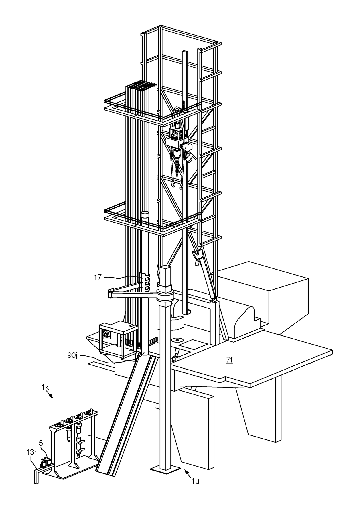
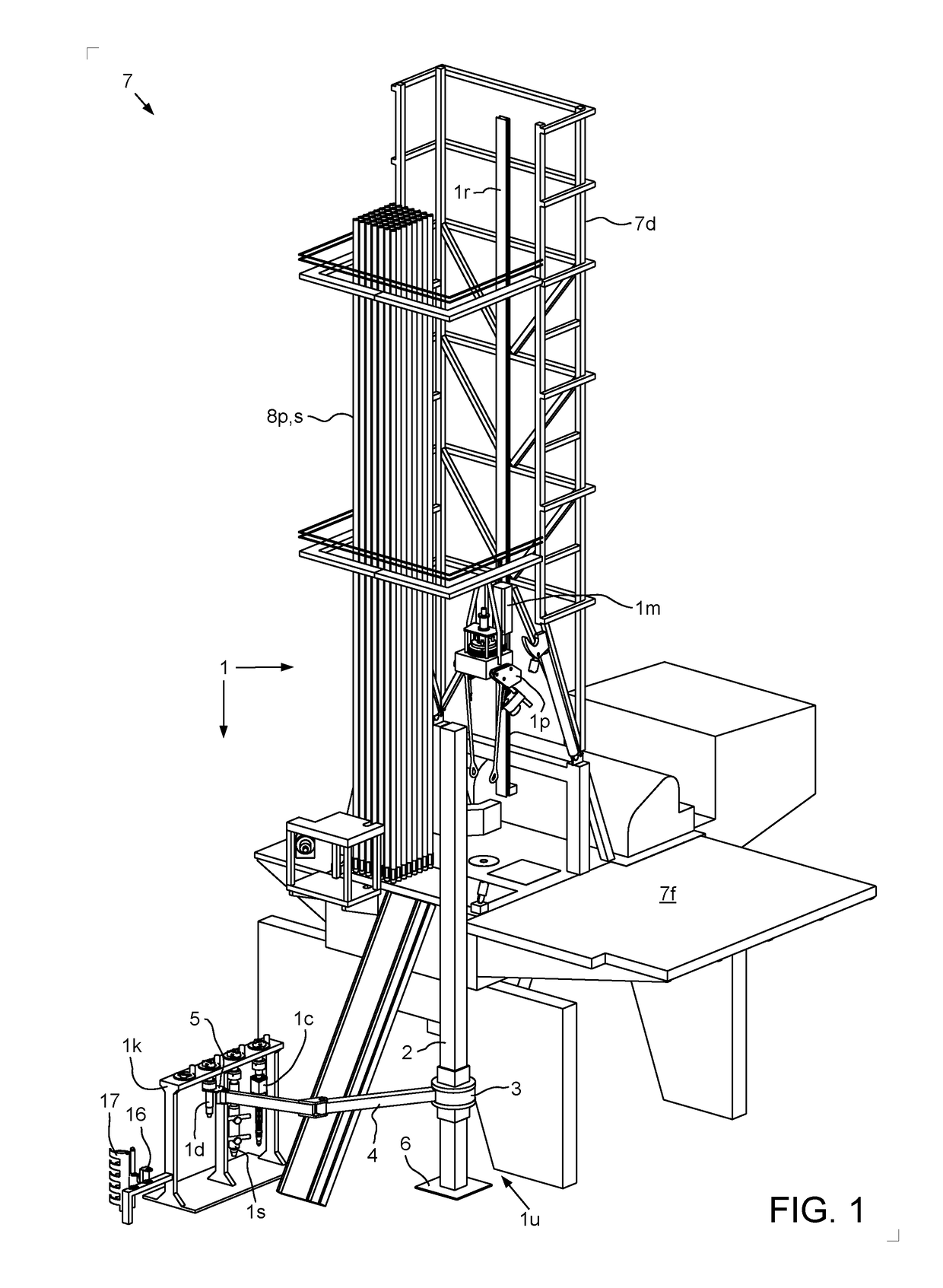
[0020]FIG. 1 illustrates a top drive system 1, according to one embodiment of the present disclosure. The top drive system 1 may be a modular top drive system and may include a linear actuator 1a (FIG. 8A), several accessory tools (e.g., casing unit 1c, a drilling unit 1d, and a cementing unit 1s) a pipe handler 1p, a unit rack 1k, a motor unit 1m, a rail 1r, and a unit handler 1u. The unit handler 1u may include a post 2, a slide hinge 3, an arm 4, a holder 5, a base 6, and one or more actuators (not shown). One or more of the accessory tools may include a genset 51 (sometimes referred to as an engine-generator set, and typically including an electric generator and an engine or motor mounted together to form a single piece of equipment).

[0021]The top drive system 1 may be assembled as part of a drilling rig 7 by connecting a lower end of the rail 1r to a floor 7f or derrick 7d of the rig and an upper end of the rail to the derrick 7d such that a front of the rail is adjacent to a d...


PUM


Abstract

A system includes an accessory tool selected from a group consisting of a casing unit, a cementing unit, and a drilling unit; and a genset mounted to the accessory tool and comprising: a fluid driven motor having an inlet and an outlet for connection to a control swivel of the system; an electric generator connected to the fluid driven motor; a manifold having an inlet for connection to the control swivel and an outlet connected an accessory tool actuator; and a control unit in communication with the electric generator and the manifold and comprising a wireless data link.

Description

BACKGROUND OF THE DISCLOSURE[0001]Field of the Disclosure[0002]The present disclosure generally relates to a genset for a top drive unit.[0003]Description of the Related Art[0004]A wellbore is formed to access hydrocarbon-bearing formations (e.g., crude oil and / or natural gas) or for geothermal power generation by the use of drilling. Drilling is accomplished by utilizing a drill bit that is mounted on the end of a drill string. To drill within the wellbore to a predetermined depth, the drill string is often rotated by a top drive on a surface rig. After drilling to a predetermined depth, the drill string and drill bit are removed and a section of casing is lowered into the wellbore. An annulus is thus formed between the string of casing and the formation. The casing string is hung from the wellhead. A cementing operation is then conducted in order to fill the annulus with cement. The casing string is cemented into the wellbore by circulating cement into the annulus defined between ...

Claims


Application Information

Patent Timeline
Patent Type & Authority Applications(United States)
IPC IPC(8): E21B19/06F01C13/00E21B33/068F01C21/18E21B19/14E21B33/05F01C1/10F01C21/00
CPCE21B19/06F01C1/103F01C13/00F01C21/008E21B33/14E21B19/14E21B33/05E21B33/068F01C21/18E21B3/02E21B19/16E21B3/022
Inventor THIEMANN, BJOERNWERN, FRANKOWNBY, JOHN FIELDINGZOUHAIR, AICAMLIESS, MARTINHEBEBRAND, CHRISTINA KARIN
Owner WEATHERFORD TECH HLDG LLC
Why Eureka
Try Eureka