Volute Design For Lower Manufacturing Cost and Radial Load Reduction

a technology of radial load reduction and valve design, which is applied in the direction of pump components, non-positive displacement fluid engines, pump components, etc., can solve the problems of increasing the difficulty of cleaning the casting properly, increasing the complexity of the casing, and long passage length of the cutwater farthest away, so as to reduce the radial load on the impeller and improve the pressure balance

Inactive Publication Date: 2017-03-09
FLUID HANDLING
View PDF5 Cites 7 Cited by
  • Summary
  • Abstract
  • Description
  • Claims
  • Application Information

AI Technical Summary

Benefits of technology

[0009]The present invention provides a new volute design that reduces the radial load on the impeller by establishing an improved pressure balance through the operating flow range of a rotodynamic pump.

Problems solved by technology

One disadvantage of the known volute design Vpa, e.g., like that shown in FIG. 1, is that the development of the opposed casing tongues results in a long passage length for cutwater farthest away from the pump discharge o, otherwise know as the upper cutwater C2.
This long length adds complexity to the casing and increases the difficulty to properly clean the casting.
This results in additional costs, and if not properly cast and cleaned will result in loss of pump performance.

Method used


Image

  • Volute Design For Lower Manufacturing Cost and Radial Load Reduction
  • Volute Design For Lower Manufacturing Cost and Radial Load Reduction

Examples


Embodiment Construction

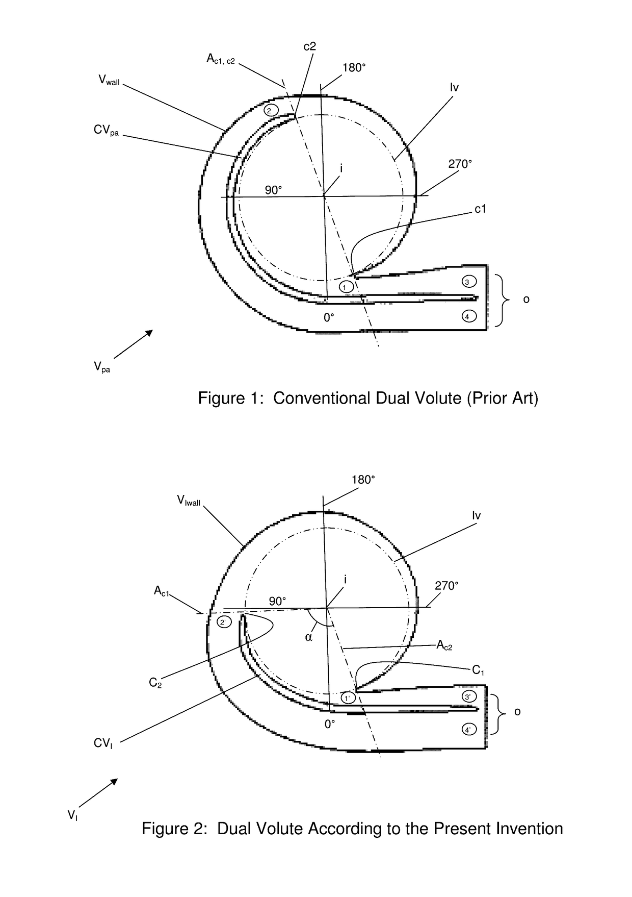
FIG. 2: The Basic Invention

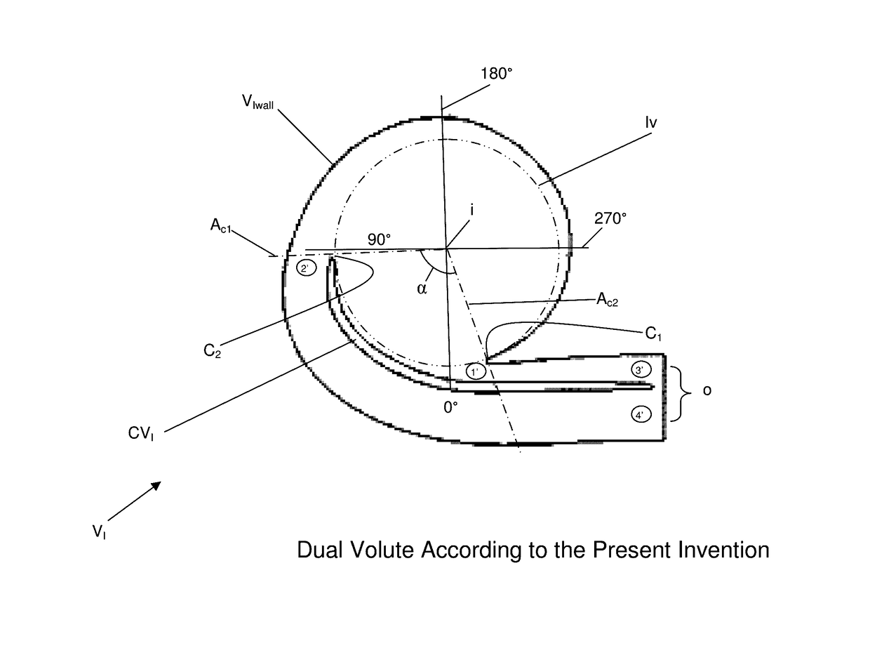
[0033]FIG. 2 shows the present invention, e.g. in the form of a volute VI for configuring in relation to a pump (not shown), such as a double volute pump. The volute VI may include one or more of the following features:[0034]a volute wall Vwall;[0035]a pump inlet i (in) for receiving a fluid being pumped;[0036]a pump discharge o (out) for providing the fluid being pumped; and[0037]a casing vane CVI.

[0038]The casing vane CVI may be configured on the volute wall Vwall forming double volutes in the volute VI and being configured with an upper cutwater C2 farthest from the pump discharge o defining an upper cutwater throat area labeled 2′ (in a circle) and an end of passage 4′ (in a circle) for the upper cutwater C2, and also configured with a lower cutwater C1 closest to the pump discharge o defining a lower cutwater throat labeled 1′ (in a circle) and a corresponding end of passage 3′ (in a circle) for the lower cutwater C1.

[0039]The upper cutwater throat ar...


PUM


Abstract

A volute for a pump featuring a volute or casing having a pump inlet for receiving a fluid being pumped, a pump discharge for providing the fluid, and a volute or casing vane forming double volutes therein. The volute has an upper cutwater farthest from the pump discharge defining an upper cutwater throat area and an end of passage for the upper cutwater, and also has a lower cutwater closest to the pump discharge defining a lower cutwater throat and a corresponding end of passage for the lower cutwater. The upper cutwater throat area is dimensioned to be greater than and not equal to the lower cutwater throat area so the upper cutwater throat area and the lower cutwater throat area provide substantially equal flow velocity at both the upper cutwater and the lower cutwater in response to an angular sweep of the fluid being pumped. The end of passage for the upper cutwater is dimensioned with an upper cutwater passage area that is greater than and not equal to a corresponding lower cutwater passage area of the corresponding end of passage for the lower cutwater so that upper and lower cutwater passage areas at the pump discharge are balanced as a function of differing rates of flow of the fluid being pumped therein and so that the fluid being pumped from associated ends of the upper and lower cutwater passage areas meets at the pump discharge with a substantially equal velocity.

Description

CROSS-REFERENCE TO RELATED APPLICATION[0001]This application claims benefit to provisional patent application Ser. No. 62 / 213,739, filed 3 Sep. 2015, which is hereby incorporated by reference in its entirety.BACKGROUND OF THE INVENTION[0002]1. Field of the Invention[0003]The present invention relates to a volute for a pump; and more particularly relates to a pump having an improved volute design.[0004]2. Brief Description of Related Art[0005]FIG. 1 shows a normal or conventional dual volute Vpa having a volute wall Vwall with a pump inlet represented by the label i and a pump outlet or discharge represented by the label o. The conventional dual volute Vpa includes a casing vane CVpa formed therein, which has a lower cutwater c1 and an upper cutwater c2 that are arranged on an axis Ac1, c2 on opposite sides of the volute wall Vwall and about 180° apart in a radial separation, e.g., consistent with that shown in FIG. 1. In FIG. 1, the radial degrees of 0°, 90°, 180°, 270° are indicate...

Claims


Application Information

Patent Timeline
Patent Type & Authority Applications(United States)
IPC IPC(8): F04D29/44F04D29/22
CPCF04D29/448F04D29/22F04D29/428F04D29/445
Inventor RUZICA, PAUL J.
Owner FLUID HANDLING
Why Eureka
Try Eureka