Multimode optical fibers operating over an extended wavelength range and system incorporating such

a multi-mode optical fiber and wavelength range technology, applied in the field of multi-mode optical fiber operating over an extended wavelength range and system, can solve the problems of limiting system reach, difficult or impossible to achieve existing multi-mode fibers with high bandwidth in a broad wavelength range, etc., to improve source and detector performance, improve photon energy conversion, and reduce optical fiber attenuation

Active Publication Date: 2017-03-09
CORNING INC
View PDF3 Cites 8 Cited by
  • Summary
  • Abstract
  • Description
  • Claims
  • Application Information

AI Technical Summary

Benefits of technology

[0018]Some of the advantages for utilizing these optical systems that utilize longer wavelength (>9000 nm) VCSELs include supporting Class 1 eye safety specifications, improved source and detector performance, lower optical fiber attenuation, better photon e...

Problems solved by technology

Although multimode fibers that are optimized for peak modal bandwidth at a wavelength near 850 nm can transmit at longer wavelengths, they exhibit low bandwidth in the 900 nm-1200 nm range, effectively limiting the system reach when such fibers are utilized with VCSELs being devel...

Method used


Image

  • Multimode optical fibers operating over an extended wavelength range and system incorporating such
  • Multimode optical fibers operating over an extended wavelength range and system incorporating such
  • Multimode optical fibers operating over an extended wavelength range and system incorporating such

Examples


Embodiment Construction

[0035]Additional features and advantages of the invention will be set forth in the detailed description which follows and will be apparent to those skilled in the art from the description or recognized by practicing the invention as described in the following description together with the claims and appended drawings.

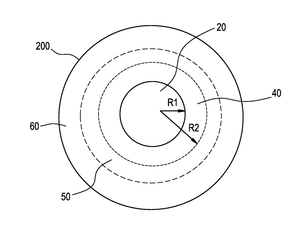
[0036]The “refractive index profile” is the relationship between refractive index or relative refractive index and waveguide fiber radius.

[0037]The “relative refractive index percent” is defined as Δ%=100×(ni2−nREF2) / 2ni2, where ni is the maximum refractive index in region i, unless otherwise specified. The relative refractive index percent is measured at 980 nm unless otherwise specified. Unless otherwise specified herein, nREF is the average refractive index of the outer annular portion 60 of the cladding, which can be calculated, for example, by taking “N” index measurements (nC1, nC2, . . . nCN) in the outer annular portion of the cladding, and calculating the avera...


PUM


Abstract

According to some embodiments, a multimode optical fiber comprises a graded index glass core with refractive index Δ1, a maximum refractive index delta Δ1MAX, and a core radius between 10 and 40 microns; and cladding region surrounding the core comprising refractive index Δ4, wherein the fiber exhibits an overfilled bandwidth exhibits an overfilled bandwidth of at least 3 GHz-km at a wavelength of 850 nm and an overfilled bandwidth of at least 1.2 GHz-km at one or more wavelengths between 980 and 1060 nm.

Description

[0001]This application claims the benefit of priority under 35 U.S.C. §119 of U.S. Provisional Application Ser. No. 61 / 941,566 filed on Feb. 19, 2014 the contents of which are relied upon and incorporated herein by reference in their entirety.[0002]The present invention relates generally to optical fibers, and more specifically to multimode optical fibers and systems incorporating such fibers.TECHNICAL BACKGROUND[0003]Multimode (MM) fibers that operate at the wavelength range centered around 850 nm are known. The bandwidth (BW) of these multimode (MM) fibers is limited mostly by inter-modal chromatic dispersion. To minimize the inter-modal chromatic dispersion, MM fibers are designed with graded index α-profiles. Current high bandwidth (greater than 1 GHz·Km) optical fibers are optimized for use at 850 nm. Some of these MM fibers also have a second operating window, with much lower BW (<1 GHz·km) centered at 1300 nm.[0004]VCSELs (vertical cavity surface-emitting lasers) being dev...

Claims


Application Information

Patent Timeline
IPC IPC(8): G02B6/028H04B10/2581H04B10/61G02B6/036H04B10/50
CPCG02B6/0288G02B6/0365H04B10/2581H04B10/6161H04B10/503G02B6/03627G02B6/0281C03B2203/26
Inventor BICKHAM, SCOTT ROBERTSONCHEN, XINLI, MING-JUN
Owner CORNING INC
Why Eureka
Try Eureka