Printed circuit board and driving method thereof
a technology of printed circuit board and driving method, which is applied in the direction of printed circuit, printed circuit details, electrical equipment, etc., can solve the problems of increasing the amount of devices in the product, the conductor area passing the large current of the backboard cannot provide low enough resistance, and the design of these products becomes more and more difficult. , to achieve the effect of increasing the resistance efficiency of the printed circuit and low resistan
- Summary
- Abstract
- Description
- Claims
- Application Information
AI Technical Summary
Benefits of technology
Problems solved by technology
Method used
Image
Examples
first embodiment
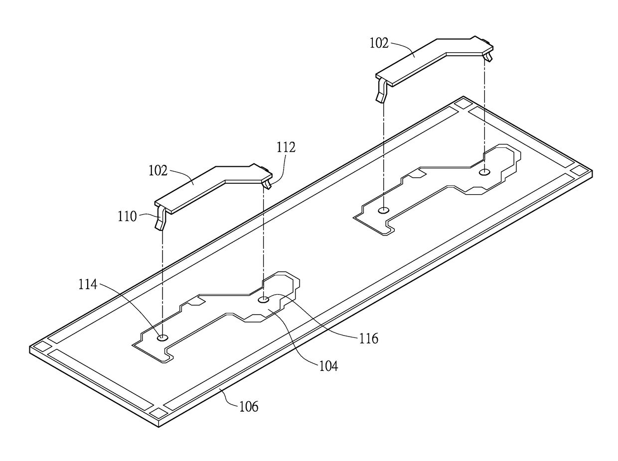
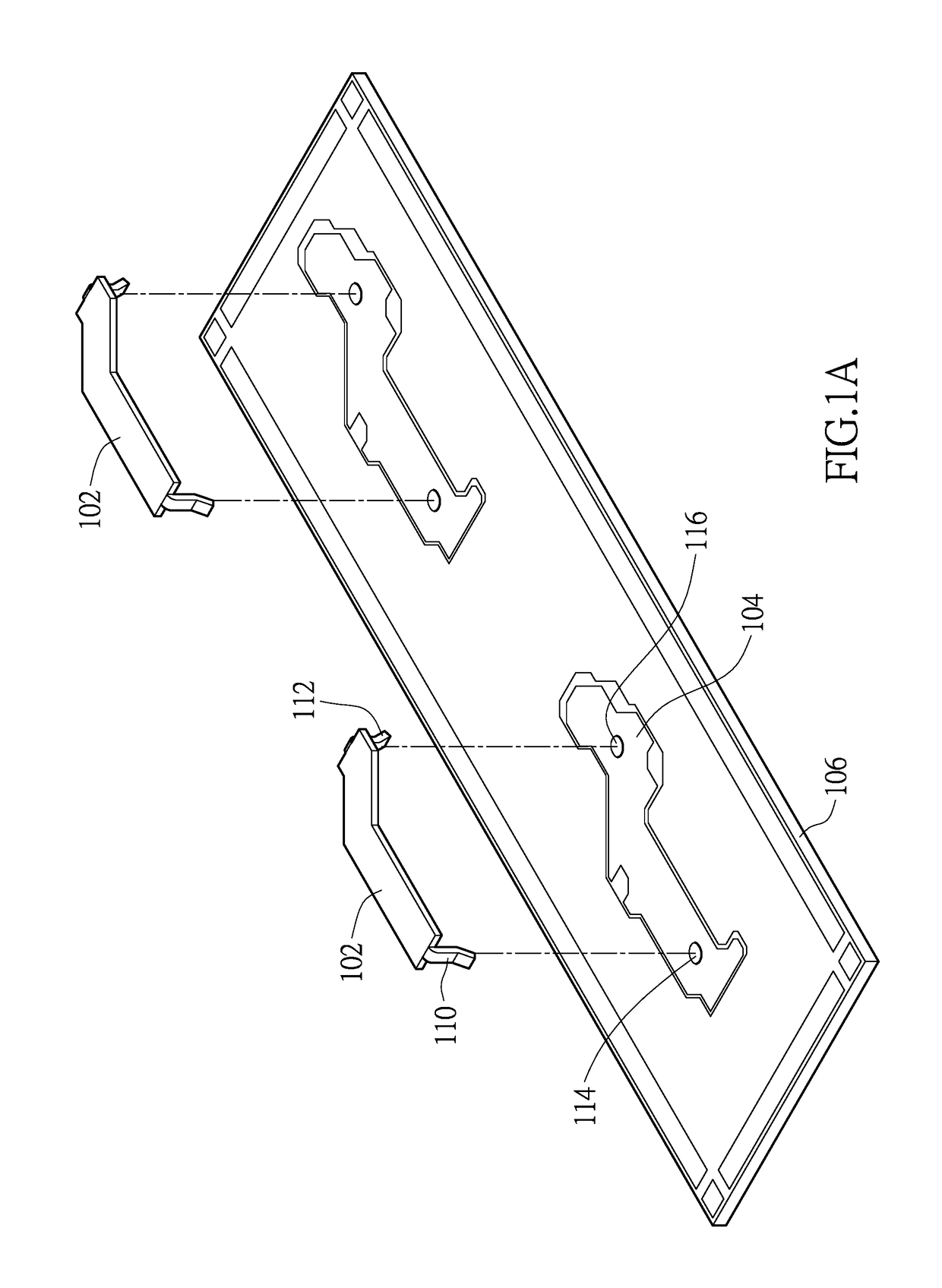
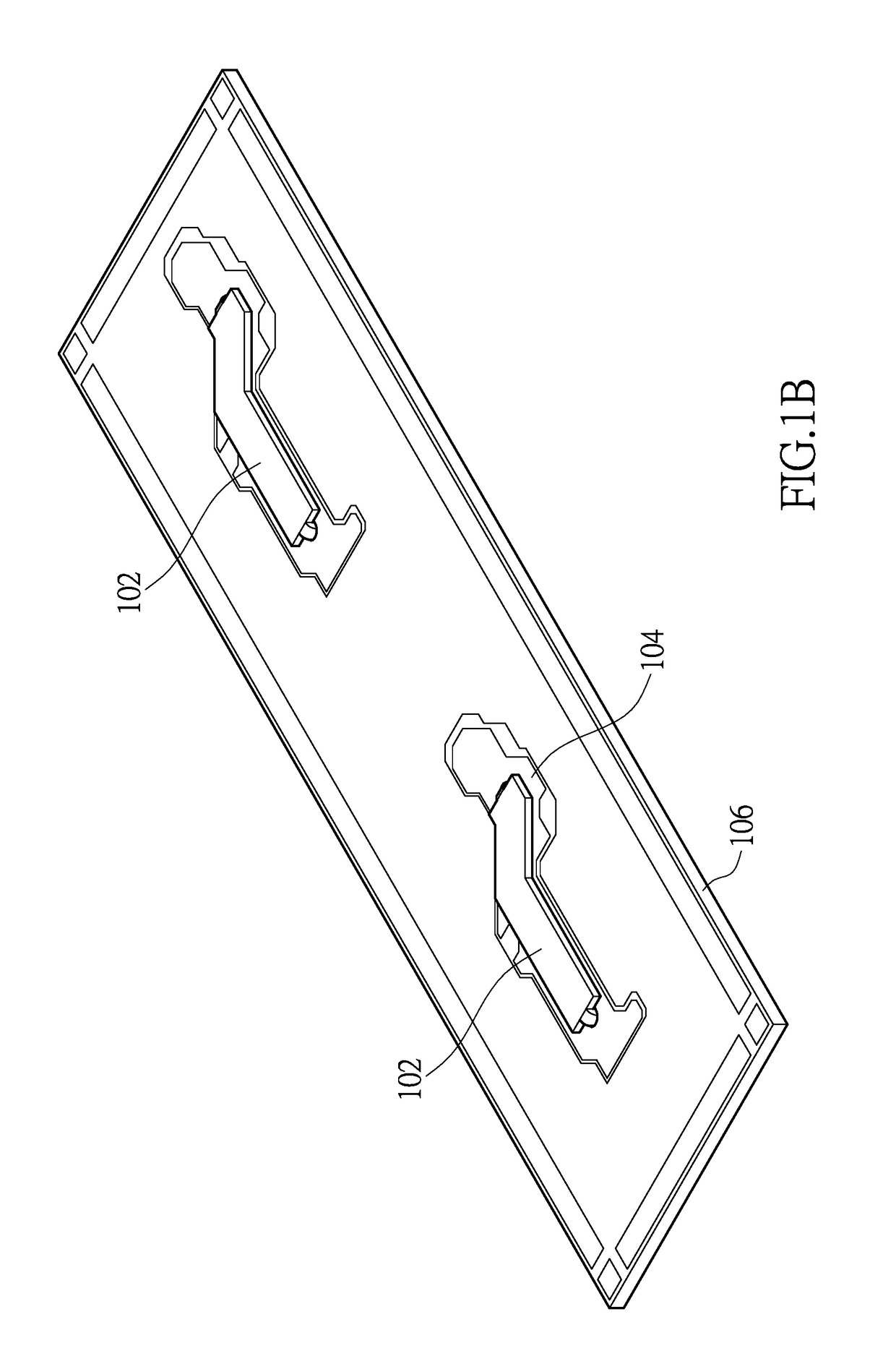
[0026]FIG. 1A shows an exploded view of the printed circuit board of an embodiment of the instant disclosure. FIG. 1B shows a three dimensional view of the printed circuit board at an intermediate stage of an embodiment of the instant disclosure. First, referring to FIG. 1A, the instant disclosure provides a printed circuit board comprising a plate body 106, a conductive pattern 104 disposed on the plate body 106 and a conductive metal plate 102 having a first terminal and a second terminal, and the first terminal and the second terminal of the conductive metal plate 102 are fixed to the plate body 106. Please refer to FIG. 1A and FIG. 1B and also FIG. 2A and FIG. 2B, wherein FIG. 2A shows a plane view of the printed circuit board at an intermediate stage, and FIG. 2B shows a cross section of the printed circuit board at an intermediate stage. The plate body 106 has a first hole 114 and a second hole 116. The first terminal of the conductive metal plate 102 has a first fastening par...
second embodiment
[0029]FIG. 3A shows a three dimensional view of a printed circuit board at an intermediate fabrication stage of the embodiment. FIG. 3B shows a cross section view of a printed circuit board at an intermediate fabrication stage of the embodiment. FIG. 3C shows a cross section view of a printed circuit board at final stage. The difference between this embodiment and the first embodiment is that an accommodating space 306 is formed between the conductive metal plate 102 and the plate body 106. The embodiment uses printing method to form a cavity 302 on the conductive metal plate 102 and form a bump 304 under the conductive metal plate 102. Because the bump 304 abuts against the plate body 106 of the printed circuit board 100, the conductive metal plate 102 is separated from the plate body 106 by a distance to form an accommodating space 306. The other part is like the first embodiment. Like elements use the same symbol and are not described again herein.
[0030]After the conductive metal...
third embodiment
[0031]FIG. 4A shows a cross section view of a printed circuit board at an intermediate fabrication stage of the embodiment. FIG. 4B shows a cross section view of a printed circuit board at final stage of the embodiment. The embodiment is similar to the second embodiment to form an accommodating space 306′ between the conductive metal plate 102′ and the plate body 106, but the difference is that the embodiment uses an arc-shaped conductive metal plate 102′. Because the conductive metal plate 102′ is arc-shaped, after the first fastening part 110 is fastened to the first hole 114 of the plate body 106 and the second fastening part 112 is fastened to the second hole 116 of the plate body 106, the bottom surface of the conductive metal plate 102′ is separated from the top surface of the plate body 106 by a distance. Therefore, an accommodating space 306′ is formed between the conductive metal plate 102′ and the plate body 106. The bottom side of the accommodating space 306′ is a plane, ...
PUM
 Abstract
Description
Claims
Application Information
 - R&D
- Intellectual Property
- Life Sciences
- Materials
- Tech Scout
- Unparalleled Data Quality
- Higher Quality Content
- 60% Fewer Hallucinations
Browse by: Latest US Patents, China's latest patents, Technical Efficacy Thesaurus, Application Domain, Technology Topic, Popular Technical Reports.
© 2025 PatSnap. All rights reserved.Legal|Privacy policy|Modern Slavery Act Transparency Statement|Sitemap|About US| Contact US: help@patsnap.com


