Method and apparatus of implementing a magnetic shield flux sweeper

a technology of magnetic shield and flux sweeper, which is applied in the field of magnetic shield, can solve the problems of increasing the difficulty of removing flux, reducing the efficiency of magnetic shield, and so as to achieve the effect of reducing the ambient magnetic field

Active Publication Date: 2017-03-09
NASA
View PDF3 Cites 7 Cited by
  • Summary
  • Abstract
  • Description
  • Claims
  • Application Information

AI Technical Summary

Benefits of technology

[0009]The present invention relates to a magnetic shield that operates by sweeping field lines to the periphery of the shield when cooled to a base operating temperature. The shield is composed of a heterostructure of different superconductors (and potentially normal metal) structures to produce a spatially varying order parameter by the proximity effect. Once a perfect Meissner state is reached throughout the shield and the shield is cooled well below the lowest transition temperature the ambient magnetic field will be reduced in a volume nearby the shield; in addition subsequent changes of magnetic field will be suppressed by the shield. Users can add these flux-sweeping magnetic-shielding structures separated by a thin insulating to magnetically sensitive regions of a wide range of electronic sensing applications, such as in lithographic circuit designs, in order to protect those regions from magnetic contamination or “crosstalk”.

Problems solved by technology

When a superconductor is cooled through the transition temperature, the critical magnetic field is zero, and it is challenging to not trap a magnetic field.
This is because once the magnetic field is nucleated inside the superconducting shield, an energy barrier to a vortex exit develops upon further cooling, making it increasing difficult to remove the flux, and the magnetic flux becomes trapped in the superconductor.

Method used


Image

  • Method and apparatus of implementing a magnetic shield flux sweeper
  • Method and apparatus of implementing a magnetic shield flux sweeper
  • Method and apparatus of implementing a magnetic shield flux sweeper

Examples


Embodiment Construction

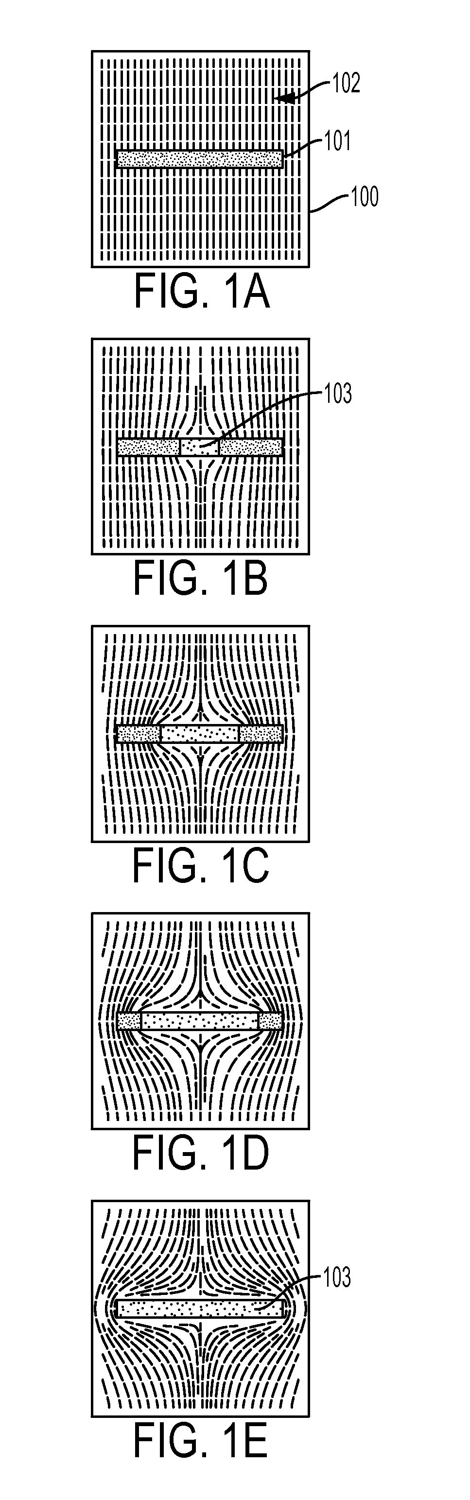
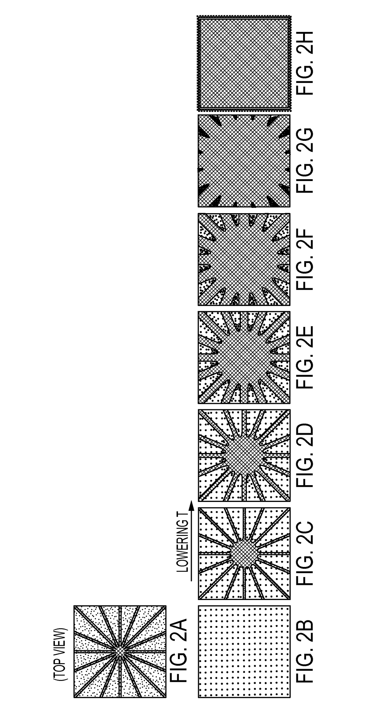
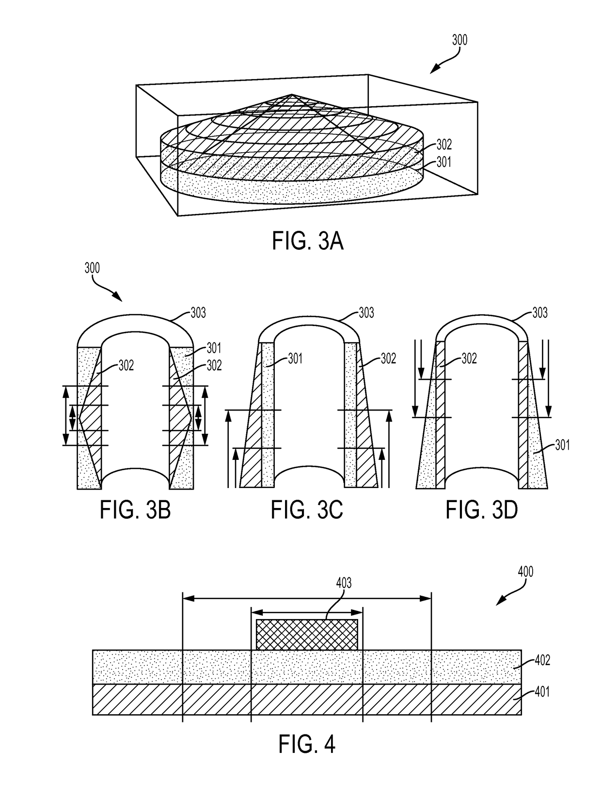
[0064]The present invention relates to a magnetic shield that operates by sweeping field lines to the periphery of the shield when cooled to a base operating temperature.

[0065]The superconducting phase is a thermodynamic state that exists in a volume of phase space below a critical temperature Tc, below a critical magnetic field Bc, and below a critical current density Jc. Two hallmarks of the superconducting state are: 1) zero direct current (DC) resistivity; and 2) a perfect diamagnetic response called the “Meissner effect”.

[0066]For both type-I and type-II superconductors, if no magnetic field lines penetrate the interior superconducting volume, it is said to be in the “Meissner state”. In the Meissner state, magnetic field lines can only enter the bounding surface of the volume up to a characteristic length called the “penetration depth” that also characterizes the length over which the Meissner screening currents are localized.

[0067]A superconducting metal cooled in a non-zero ...


PUM


Abstract

The present invention relates to a method and apparatus of protecting magnetically sensitive devices with a shield, including: a non-superconducting metal or lower transition temperature (Tc) material compared to a higher transition temperature material, disposed in a magnetic field; means for creating a spatially varying order parameter's |Ψ(r, T)|2 in a non-superconducting metal or a lower transition temperature material; wherein a spatially varying order parameter is created by a proximity effect, such that the non-superconducting metal or the lower transition temperature material becomes superconductive as a temperature is lowered, creating a flux-free Meissner state at a center thereof, in order to sweep magnetic flux lines to the periphery.

Description

BACKGROUND OF THE INVENTION[0001]1. Field of the Invention[0002]The present invention relates to a magnetic shield that operates by sweeping magnetic flux lines to the periphery of the shield when cooled to a base operating temperature. Users can add the flux-sweeping magnetic-shield structure to magnetically sensitive regions of a wide range of electronic sensing applications, such as in lithographic circuit designs, in order to protect those regions from magnetic contamination or “crosstalk”.[0003]2. Description of the Related Art[0004]The need for improved sensing capabilities motivates low temperature detectors technologies. Operating devices at low temperatures fundamentally reduces the detectors thermal noise environment making systems capable of sensing smaller energy signals. In addition to a reduced thermal noise, lower temperatures allows superconductivity to be used in sensing applications. Superconductors offer a plethora of remarkable physical properties such as zero di...

Claims


Application Information

Patent Timeline
Patent Type & Authority Applications(United States)
IPC IPC(8): H05K9/00
CPCH05K9/0071H05K9/0077G01R33/0076G01R33/025
Inventor SADLEIR, JOHN E.
Owner NASA
Why Eureka
Try Eureka