Wind turbine station and tower with vertical storage tanks

a technology of vertical storage tanks and wind turbines, which is applied in the direction of machines/engines, mechanical equipment, greenhouse gas reduction, etc., can solve the problems of increasing the cost of overhead or underground cables from the nearest grid to the end user, increasing storage tanks, and increasing the height of wind turbine blades. , the effect of increasing the cost of installation and eliminating the cost of separate towers

Inactive Publication Date: 2017-03-16
ENIS BEN M +1
View PDF52 Cites 4 Cited by
  • Summary
  • Abstract
  • Description
  • Claims
  • Application Information

AI Technical Summary

Benefits of technology

[0028]One of the advantages of the wind turbine station and tower of the present invention is that the builder of the facility can avoid the high cost of having to construct both a separate tower and a separate storage tank for storing compressed air, wherein in current practice, the cost of the tower itself can be more than fifty percent of the total cost of the station. This way, the cost of separately providing the tower and storage tank can be eliminated, thereby making these systems more cost-effective to install.
[0029]Another advantage is that the height of the wind turbine blades can be increased substantially by creating a strengthened tower that can better resist the wind forces and resulting bending moment forces that can be applied to the top of the tower as the wind engages the turbine blades at higher elevations. This not only allows the turbine blades to be situated higher to access greater wind speeds, and therefore, achieve increased efficiencies, but also enables the wind turbine stations to be provided with greater storage capacities and located closer to potential upwind obstructions, i.e., by allowing the blades to be positioned above the height of the obstruction, it becomes possible to locate the tower closer to the obstruction.

Problems solved by technology

While attempts have been made to reduce reliance on foreign oil, many energy experts fear that some of these resources, including oil, gas and coal, may someday run out.
And due to increased energy demands, and energy costs, energy providers have begun to seriously consider the feasibility and use of energy derived from those sources including the sun and wind.
In some remote areas, however, the cost of running overhead or underground cables from the nearest grid to the end user can be prohibitively high, and therefore, electrical power is not always readily available.
And to make matters worse, the cost of installing an energy generating facility in such locations is normally incurred by the end user, such as where land is privately owned and public utility companies have no obligation to service those areas.
Moreover, even if power lines are provided to these locations, significant power losses can occur due to great distances, wherein the energy that travels through the lines can be significantly diminished by the time it reaches its destination.
One drawback to using wind as an energy source, however, is that the wind does not always blow, and even if it does, it does not always blow consistently at the same speed, i.e., it is often unpredictable, and therefore, it is not always a reliable form of energy, and the amount of wind derived energy will differ significantly from time to time and from location to location.
While some attempts have been made to store energy produced by the wind so it can be used later during peak demand periods, or when the wind is not blowing hard enough, these attempts have not yet produced systems that are sufficiently efficient, nor have they been able to reduce the costs and difficulties associated with using wind as an energy source.
For example, past attempts include using batteries to store electricity as well as large steel tanks or underground caverns to store compressed air energy, but these attempts have not been successful mainly due to their excessive costs.
Indeed, when taking into account the cost of constructing wind turbines, etc., and the cost of constructing the storage tanks and other related equipment, including the towers, as well as the potential energy losses attributable to converting energy from one form to another, it has not always been cost effective to develop these types of systems.
And, when taking into account the amount of storage space normally required for a facility like this to store energy, it is often cost prohibitive to build large steel tanks and vessels to hold the compressed air needed to supply the necessary power.
And, while the cost of using an existing underground cavern for storing compressed air is relatively low compared to using steel tanks, the downside is that there are only a few areas in existence that have caverns large enough and airtight enough for storing compressed air energy, and even when there is such a site, the facility that uses the cavern will have to be built directly above the cavern, which may or may not be feasible or even possible.

Method used


Image

  • Wind turbine station and tower with vertical storage tanks
  • Wind turbine station and tower with vertical storage tanks
  • Wind turbine station and tower with vertical storage tanks

Examples


Embodiment Construction

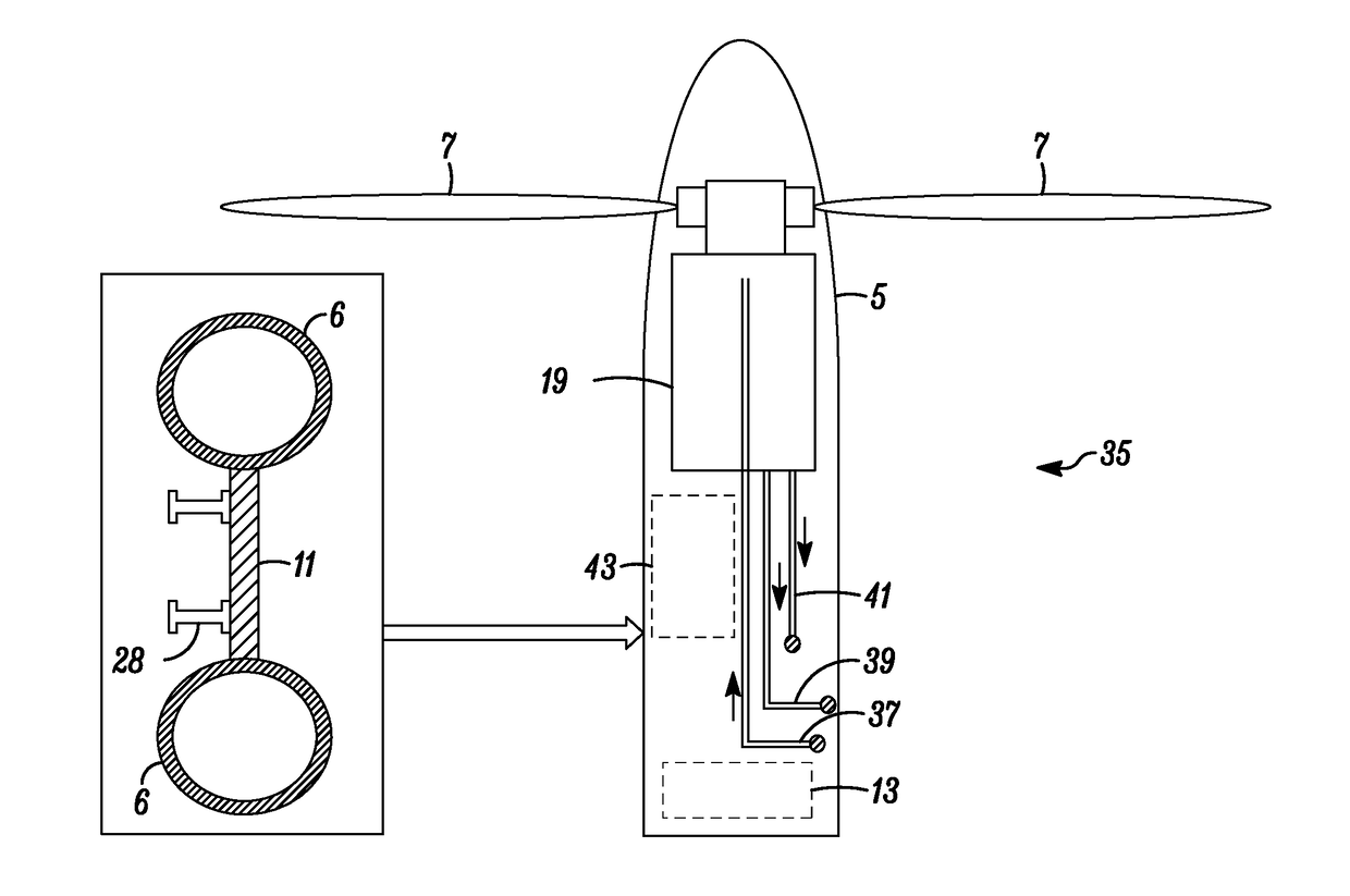
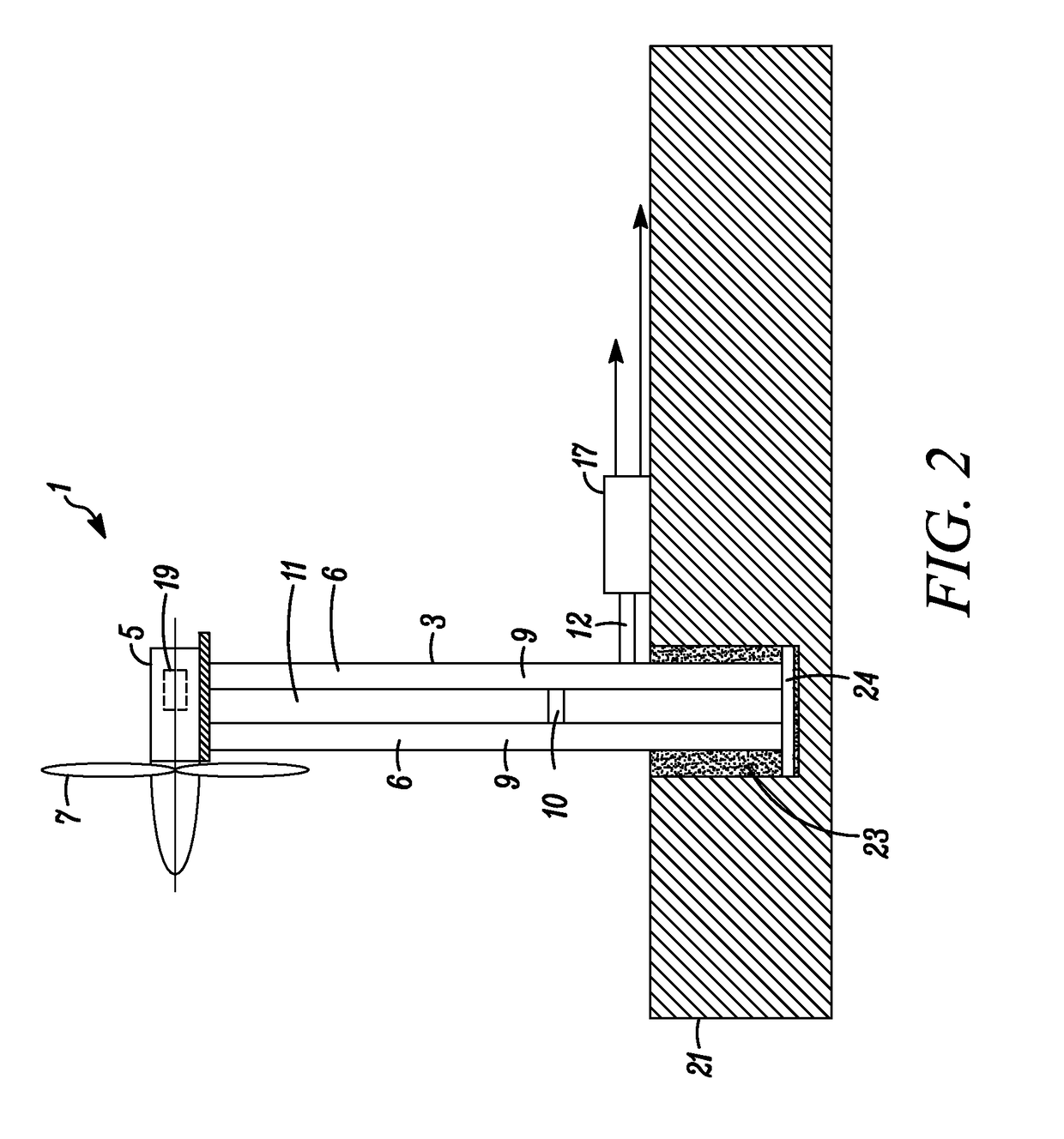
[0043]FIG. 1 shows a wind turbine station 1 and tower 3 of the present invention wherein a wind turbine drive mechanism is located inside a nacelle 5 located on top of tower 3, and wind turbine blades 7 are connected thereto and allowed to rotate. Tower 3 preferably comprises two large vertically oriented storage tanks or vessels 9, which are extended upward from the ground, and which serve to not only support the wind turbine blades 7 high in the air, but also to provide storage volume space for the compressed air energy produced by station 1.

[0044]In the preferred embodiment, at least two vertically oriented tanks or vessels 9, extended parallel to one another, with their longitudinal axis extending substantially vertical, are provided and installed per tower 3, although not necessarily so, i.e., a tower 3 can have one tank or vessel 9, but preferably two or more tanks or vessels 9, as will be discussed. Preferably, as shown in the cross section drawing of FIG. 3, two tanks or ves...


PUM


Abstract

The invention relates to a wind turbine station and tower as well as wind farms using them, wherein each wind turbine station comprises a tower consisting of preferably two or more vertically oriented compressed air pressure storage tanks or vessels. The tanks or vessels are preferably comprised of vertically oriented elongated steel pipes that are extended parallel to each other and spaced apart with a steel web between them for reinforcing the strength and rigidity and moment resistance of the tower to resist lateral wind forces that may be applied to the top of the tower. Various numbers and confirmations of pipes are contemplated to provide the advantages described herein.

Description

FIELD OF THE INVENTION[0001]The present invention relates to wind turbines for the generation of electricity and other forms of energy and in particular to a wind turbine station and tower with vertically oriented storage tanks or vessels for storing compressed air energy.BACKGROUND OF THE INVENTION[0002]While attempts have been made to reduce reliance on foreign oil, many energy experts fear that some of these resources, including oil, gas and coal, may someday run out. Because of these concerns, projects have been initiated in an attempt to harness energy from what are often referred to as natural “alternative” sources—sources that will never become depleted. And due to increased energy demands, and energy costs, energy providers have begun to seriously consider the feasibility and use of energy derived from those sources including the sun and wind.[0003]Most populated areas of the country have adequate availability of electricity, such as those provided by local utility companies...

Claims


Application Information

Patent Timeline
Patent Type & Authority Applications(United States)
IPC IPC(8): F03D9/00F03D80/80F03D80/60F03D1/06F03D9/17
CPCF03D9/001F03D1/06F03D9/005F03D80/88F03D80/60F03D80/82F03D9/17F03D9/18Y02E10/72Y02E60/16Y02E70/30
Inventor ENIS, BEN M.LIEBERMAN, PAUL
Owner ENIS BEN M
Why Eureka
Try Eureka