Camera and camera accessory

a technology for cameras and accessories, applied in the field of cameras and camera accessories, can solve the problems of reducing the size of the camera, affecting the miniaturization of the camera, and generating noise from the motor, so as to reduce the size thereby, reduce the electrical loss due to wiring resistance, and improve the effect of noise toleran

Active Publication Date: 2017-03-16
CANON KK
View PDF4 Cites 13 Cited by
  • Summary
  • Abstract
  • Description
  • Claims
  • Application Information

AI Technical Summary

Benefits of technology

[0012]The present invention provides a camera and a camera accessory whose contact occupied angular range in their mounts is small and whose size thereby can be reduced. Moreover, the present invention provides a camera and a camera accessory in which electrical loss due to wiring resistance is reduced and which have noise tolerance.

Problems solved by technology

The camera and accessory each provided with such a mount (particularly, a molded mount) holding the contact pins have the following problems.
Such a configuration increases an angular range occupied by the camera side contact pins (that is, a contact occupied angular range) in the camera side mount, which impedes miniaturization of the camera.
On the other hand, the camera is provided with a motor as an actuator to drive a shutter or the like; the motor generates noise.
The noise affects control of the accessory, which causes erroneous operation of the accessory.
However, a long length wiring is likely to increase electrical loss due to wiring resistance.

Method used


Image

  • Camera and camera accessory
  • Camera and camera accessory
  • Camera and camera accessory

Examples


embodiment 1

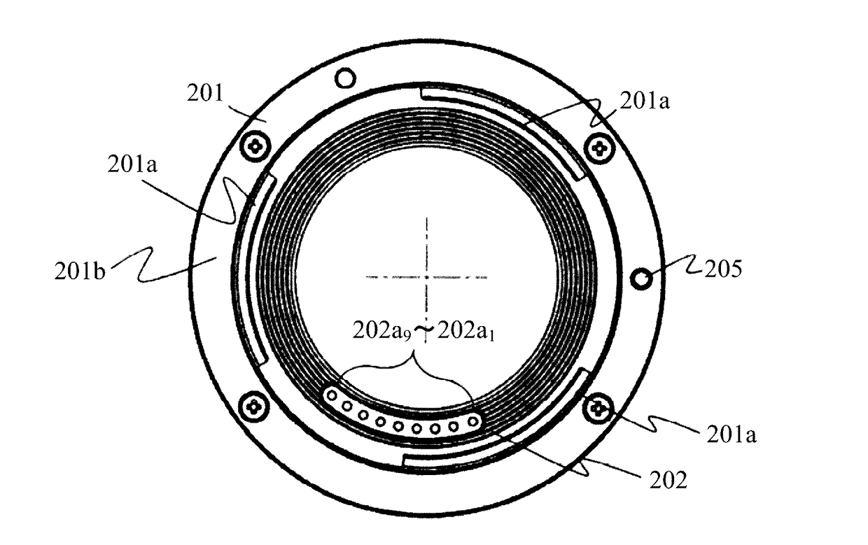
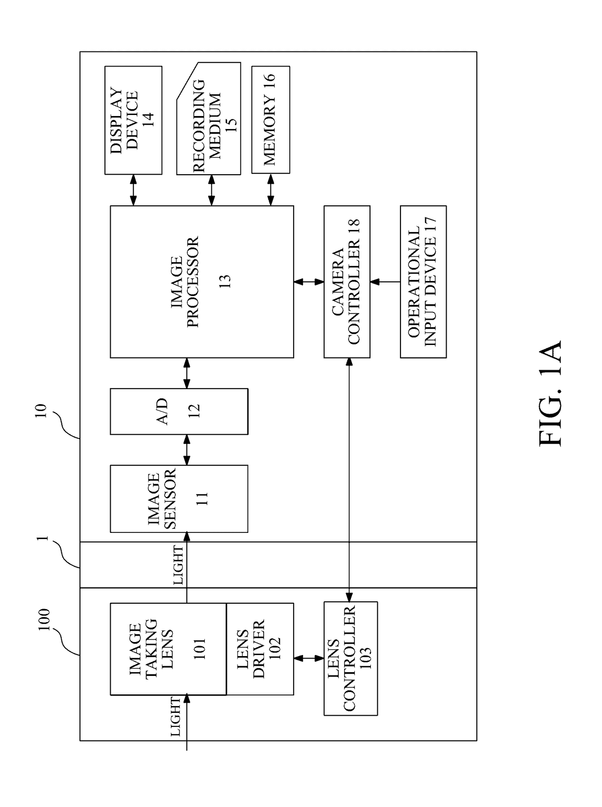
[0044]FIG. 1A shows an interchangeable lens 100 as a camera accessory and a camera 10 to which the interchangeable lens 100 is detachably (that is, interchangeably) attached, which are Embodiment 1 of the present invention and constitute a camera system. The camera 10 and the interchangeable lens 100 each have a mount 1 provided with electrical contacts for supplying source power from the camera 10 to the interchangeable lens 100 and for performing communication therebetween. Although this embodiment describes the interchangeable lens as the camera accessory detachably attachable to the camera, other camera accessories are also included in other embodiments of the present invention.

[0045]The camera 10 includes an image sensor (image pickup element) 11 that photoelectrically converts an object image as an optical image formed by an image taking lens 101 housed in the interchangeable lens 100 and outputs an analog electrical signal. Moreover, the camera 10 includes an A / D converter 12...

embodiment 2

[0173]FIGS. 11A to 11C show, as a second embodiment of the present invention, a case of satisfying the above-described conditions (2) and (3), but not satisfying the conditions (1) and (4). In this embodiment, the pitch P2 and the interval Q2 between the mutually adjacent first and second lens side contact patterns 302ay and 302ay+1 are larger than the pitch P1 and the interval Q1 between the mutually adjacent second lens side contact patterns 302ax and 302ax+1. Moreover, the pitch P2 between the mutually adjacent first and second camera side contact pins 202ay and 202ay+1 is also larger than the pitch P1 between the mutually adjacent second camera side contact pins 202ax and 202ax+1.

[0174]However, the width of the first lens side contact pattern 302ay is equal to L1 that is the width of the second lens side contact pattern 302ax (302ay+1). However, L1 in this embodiment is set to be larger than L1 shown in Embodiment 1, and is set to be larger than the possible pin contact area WW,...


PUM


Abstract

The camera side mount is brought, by relative rotation with the accessory side mount, from a first state where each accessory side bayonet claw is inserted between the camera side bayonet claws into a second state where the camera side and accessory side bayonet claws engage with each other. The leaf spring biasing the camera side contact pins in the protruding direction is disposed between the camera side mount and the camera body. When the camera being in the normal position is viewed from the direction facing the camera side mount, the leaf spring extends from both sides of the mount center line, which extends from the center of the camera side mount in the direction of gravity, toward the camera side contact pins. The camera side contact pins are arranged at positions other than a position on the mount center line.

Description

CROSS-REFERENCE TO RELATED APPLICATIONS[0001]This application is a divisional of application Ser. No. 13 / 856,652, filed Apr. 4, 2013 the entire disclosure of which is hereby incorporated by reference.BACKGROUND OF THE INVENTION[0002]The present invention relates to a camera and a camera accessory interchangeably attachable to the camera such as an interchangeable lens.[0003]Such camera accessories (each hereinafter simply referred to as “an accessory”) receive, in a state of being attached to a camera, supply of power from the camera and perform communication of commands, data or the like with the camera. In order to perform such supply of power and communication, an attachment portion (mount) of the camera and that of the accessory are provided with multiple electrical contacts (each hereinafter simply referred to as “a contact”) in which paired ones are brought into contact with each other to establish electrical connection. Moreover, as a method of the attachment (coupling) of th...

Claims


Application Information

Patent Timeline
Patent Type & Authority Applications(United States)
IPC IPC(8): G03B17/56G03B17/14
CPCG03B17/14G03B17/565G03B2206/00G03B17/566
Inventor NISHIO, TETSUYAKONNO, YOSHIHIKOTOKUNAGA, TATSUYUKIHASEGAWA, TAKASHIKIKUCHI, HIROSHISUGAWARA, AZUSA
Owner CANON KK
Why Eureka
Try Eureka