Carrier for unmanned aerial vehicle

a carrier and aerial vehicle technology, applied in the field of carriers for aerial vehicles, can solve the problems of difficult multi-dimensional photography limited shot angles of existing unmanned vehicles, and inability to perform limited shot angles before running into obstructions, so as to improve the flexibility and operability of payloads, reduce the volume and weight of gimbal mechanisms, and improve the stability of movement

Inactive Publication Date: 2017-03-16
SZ DJI OSMO TECH CO LTD
View PDF1 Cites 50 Cited by
  • Summary
  • Abstract
  • Description
  • Claims
  • Application Information

AI Technical Summary

Benefits of technology

[0005]The carrier herein may comprise one or more actuators or actuation assemblies that may drive the payload to move relative to the central body or propulsion units of the UAV. To further improve the flexibility and operability of the payload, a gimbal or gimbal mechanism may be part of the carrier and may connect to the payload. A gimbal mechanism as described herein may provide rotation of the payload about one or more different axes, wherein the rotation about the different axes is controlled by respective different actuators that may be actuated independently of one another. The actuators may optionally be fixed in position and orientation relative to one another, such that none of the actuators is driven by the other. Therefore, the gimbal mechanism can control movement of the payload about various degrees of freedom in a parallel manner. The gimbal mechanisms may have a compact configuration that allows for minimizing or reducing the volume and weight of the gimbal mechanisms, while improving the stability of movement provided by the gimbal mechanisms.

Problems solved by technology

However, existing unmanned vehicles equipped with an imaging device can be less than ideal in photography.
In most instances, due to restrictions imposed by a coupling of the imaging device to the unmanned vehicles, the existing unmanned vehicles may only be capable of performing limited shot angles before running into obstructions.
Therefore, it would be hard for the existing unmanned vehicle to achieve multidimensional photography, for example, for a panoramic image.

Method used


Image

  • Carrier for unmanned aerial vehicle
  • Carrier for unmanned aerial vehicle
  • Carrier for unmanned aerial vehicle

Examples


Embodiment Construction

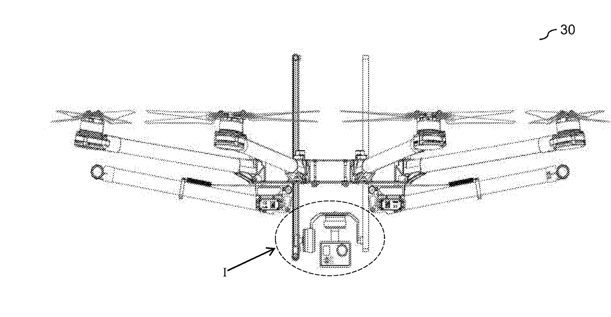
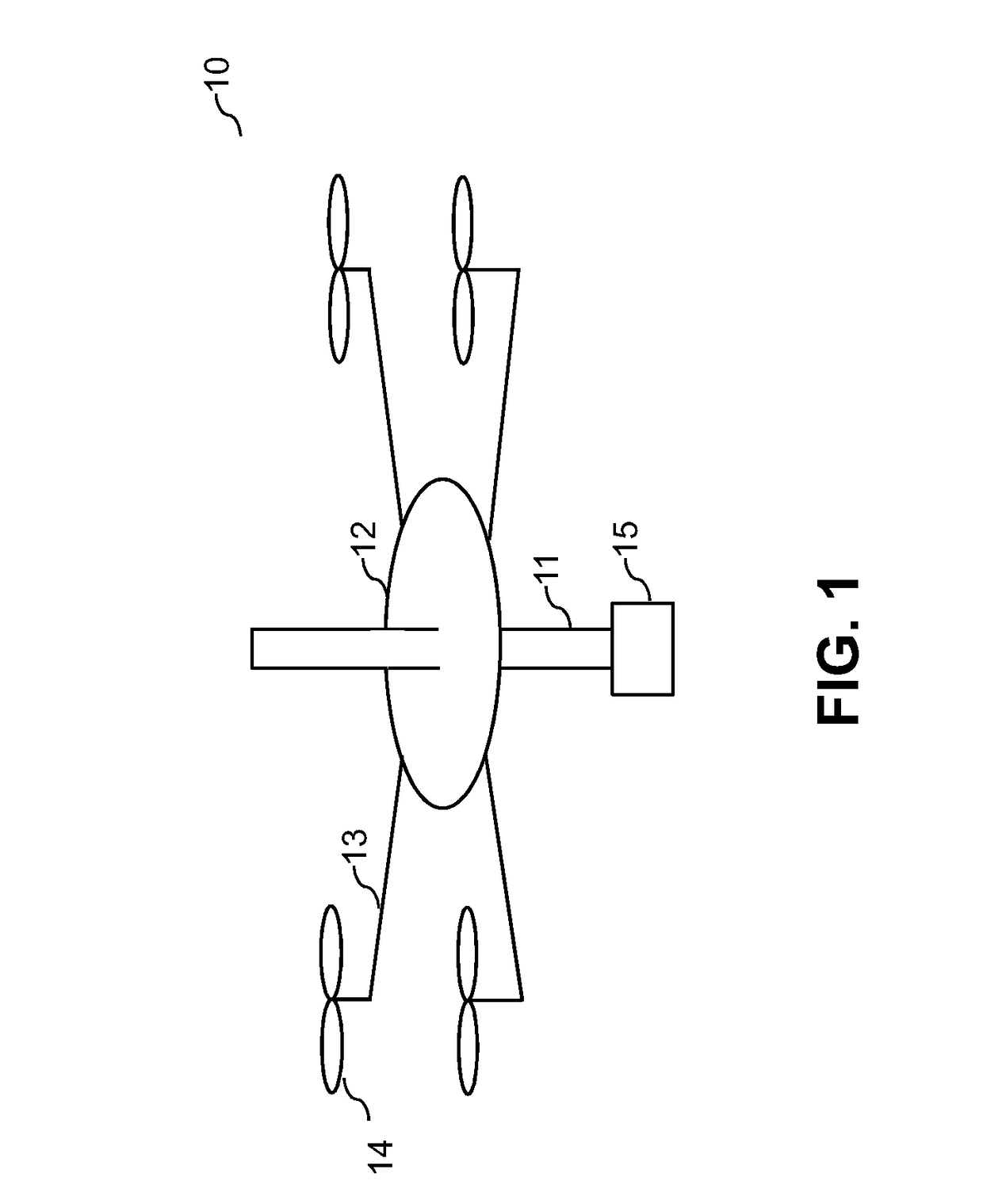
[0040]Devices, mechanisms and methods as described herein provide controlling the positioning of a payload relative to one or more components or parts of a vehicle, such as relative to a central body or propulsion units of an unmanned aerial vehicle (UAV). The payload may be coupled to the vehicle through a carrier and the carrier may permit or drive the payload to translate relative to one or more components of the vehicle. The carrier may be configured to support the payload and drive the payload to move using one or more actuators or actuation assemblies. The carrier may comprise one or more guides and one, two, or more actuators. One or more actuators may be configured to permit the payload to translate with respect to the one or more guides. Another one or more actuators may be configured to permit the payload to rotate about one or more axes of rotation with respect to the one or more guides. In some embodiments, the one or more guides may be one or more bars or rods arranged ...


PUM


Abstract

The invention describes devices and methods for controlling positioning of a payload on an unmanned aerial vehicle. A carrier as described herein may provide movement of a payload relative to a central body or one or more propulsion units of the unmanned aerial vehicle. The payload may move above and below the central body or the one or more propulsion units. The carrier may comprise one or more guides, a first actuator and a second actuator. The first actuator may permit the payload to translate with respect to the one or more guides and the second actuator may permit the payload to rotate about one or more axes of rotation with respect to the one or more guides. Therefore, the positioning of the payload may be well controlled, and movability and maneuverability of the payload may be increased.

Description

CROSS-REFERENCE[0001]This application is a continuation application of International Application No. PCT / CN2015 / 089465, filed on Sep. 11, 2015, the content of which is hereby incorporated by reference in its entirety.BACKGROUND OF THE INVENTION[0002]Unmanned vehicles, such as ground vehicles, aerial vehicles, surface vehicles, underwater vehicles, and spacecraft, have been developed for a wide range of applications including surveillance, search and rescue operations, exploration, and other fields. In some instances, unmanned vehicles may be equipped with a payload configured to collect data during operation. For example, unmanned aerial vehicles (UAV) may be equipped with imaging devices, such as cameras, for aerial photography. A payload may be coupled to an unmanned vehicle via a carrier that provides movement of the payload in one or more degrees of freedom.[0003]However, existing unmanned vehicles equipped with an imaging device can be less than ideal in photography. In most in...

Claims


Application Information

Patent Timeline
Patent Type & Authority Applications(United States)
IPC IPC(8): G05D1/00B64D47/08B64C39/02
CPCG05D1/0094G05D1/0011B64D47/08B64C39/024H04N5/00G03B15/006G03B17/561G03B2205/0007F16M11/123F16M11/18F16M11/24F16M13/02F16M2200/041H04N23/57H04N23/60H04N23/685H04N23/6812B64U10/13B64U2101/30B64U2201/20F16M11/04
Inventor LIU, HAO
Owner SZ DJI OSMO TECH CO LTD
Why Eureka
Try Eureka