Systems and methods for wireless power charging

a wireless power charging and wireless technology, applied in the field of wireless power charging systems, can solve the problems of not considering user mobility, unable to transmit energy at any meaningful distance, and most conventional techniques cannot be outside of a narrow window of operability,

Active Publication Date: 2017-03-16
ENERGOUS CORPORATION
View PDF5 Cites 208 Cited by
  • Summary
  • Abstract
  • Description
  • Claims
  • Application Information

AI Technical Summary

Benefits of technology

[0030]In another embodiment, a method for wireless power transmission, comprises transmitting, by a transmitter, power waves that converge in a three dimensional space to form a one or more pockets of energy at a predetermined location for receiving by antenna elements of a receiver, wherein the receiver harvests power from the one or more pockets of energy at the predetermined location; acquiring, by a plurality of sensors in communication with the transmitter, data indicating presence of a living being or a sensitive object; obtaining, by the transmitter, information relating to a location of the living being or the sensitive object based upon the data indicating the presence of the living being or the sensitive object; and at least reducing, by the transmitter, the power level of the power waves that converge in the three dimensional space to form the one or more pockets of energy at the predetermined location, when the data relating to the presence of the living being or the sensitive object indicates that the living being or the sensitive object is proximate to the three dimensional space at the predetermined location.

Problems solved by technology

However, most conventional techniques are unable to transmit energy at any meaningful distance.
Other conventional solutions may not contemplate user mobility for users who are charging their mobile devices or such solutions do not allow devices to be outside of a narrow window of operability.
Conventional systems typically attempt to proximately locate an electronic device, so there are no capabilities for identifying and mapping the spectrum of available devices to charge, for example, in a large coffee shop, household, office building, or other three-dimensional space in which electrical devices could potentially move around.

Method used


Image

  • Systems and methods for wireless power charging
  • Systems and methods for wireless power charging
  • Systems and methods for wireless power charging

Examples


Embodiment Construction

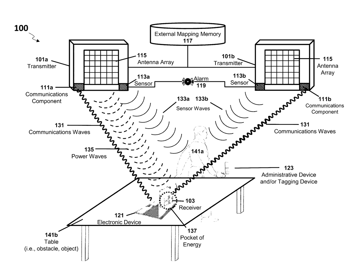
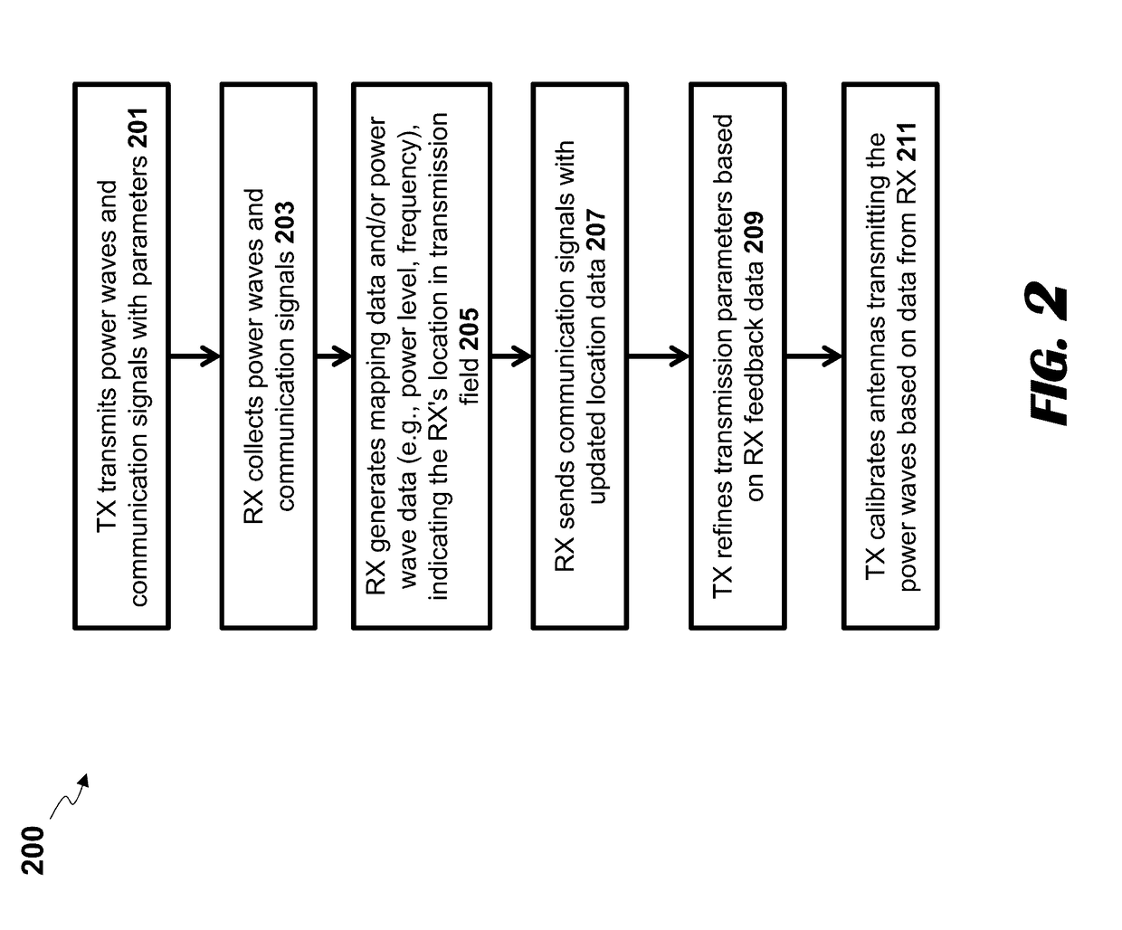
[0087]The present disclosure is here described in detail with reference to embodiments illustrated in the drawings, which form a part here. Other embodiments may be used and / or other changes may be made without departing from the spirit or scope of the present disclosure. The illustrative embodiments described in the detailed description are not meant to be limiting of the subject matter presented here.

[0088]Reference will now be made to the exemplary embodiments illustrated in the drawings, and specific language will be used here to describe the same. It will nevertheless be understood that no limitation of the scope of the invention is thereby intended. Alterations and further modifications of the inventive features illustrated here, and additional applications of the principles of the inventions as illustrated here, which would occur to one skilled in the relevant art and having possession of this disclosure, are to be considered within the scope of the invention.

[0089]In the fol...


PUM


Abstract

Embodiments disclosed herein may generate and transmit power waves that, as result of their physical waveform characteristics (e.g., frequency, amplitude, phase, gain, direction), converge at a predetermined location in a transmission field to generate a pocket of energy. Receivers associated with an electronic device being powered by the wireless charging system, may extract energy from these pockets of energy and then convert that energy into usable electric power for the electronic device associated with a receiver. The pockets of energy may manifest as a three-dimensional field (e.g., transmission field) where energy may be harvested by a receiver positioned within or nearby the pocket of energy.

Description

TECHNICAL FIELD OF DISCLOSURE[0001]This application generally relates to wireless charging systems and the hardware and software components used in such systems.BACKGROUND[0002]Numerous attempts have been made to wirelessly transmit energy to electronic devices, where a receiver device can consume the transmission and convert it to electrical energy. However, most conventional techniques are unable to transmit energy at any meaningful distance. For example, magnetic resonance provides electric power to devices without requiring an electronic device to be wired to a power resonator. However, the electronic device is required to be proximately located to a coil of the power resonator (i.e., within a magnetic field). Other conventional solutions may not contemplate user mobility for users who are charging their mobile devices or such solutions do not allow devices to be outside of a narrow window of operability.[0003]Wirelessly powering a remote electronic device requires a means for i...

Claims


Application Information

Patent Timeline
Patent Type & Authority Applications(United States)
IPC IPC(8): H02J7/02H02J7/04H04B5/00G06V30/224
CPCH02J7/025H04B5/0037H02J2007/0096H02J7/027H02J7/045H02J50/90H02J50/80H02J50/60G06T7/60H02J7/00034H04N7/18H04N5/04G06V30/224G06V10/42H02J50/20H02J7/00714
Inventor LEABMAN, MICHAEL A.
Owner ENERGOUS CORPORATION
Why Eureka
Try Eureka