Multi-Stage Led Driving Circuit Capable of Eliminating Current Undershoot

a driving circuit and multi-stage technology, applied in the direction of lighting devices, electrical devices, light sources, etc., can solve the problems of current undershoot, predetermined threshold voltages are not likely suitable for different samples of led modules,

Inactive Publication Date: 2017-03-16
LUXMILL ELECTRONICS
View PDF8 Cites 9 Cited by
  • Summary
  • Abstract
  • Description
  • Claims
  • Application Information

AI Technical Summary

Benefits of technology

[0026]wherein the control unit initially makes each of the control signals SW1-SWM exhibiting an active state to turn on each of the switch units, and then, when two adjacent current sensing signals CSj and CSj+1 of the current sensing signals CS1-CSM are detected to have a ratio CSj/CSj+1 smaller than K, j being a positive integer ranging from 1 to M−1, K being a positive real number greater than 1, makes a control signal SWj of the control signals SW1-SWM exhibiting an in...

Problems solved by technology

However, as the current-voltage characteristic curves of the LEDs are likely different, therefore, the predetermined threshold voltages are not likely suitable for different samples of the LED module.
In other words, as randomly selected LEDs tend to have different forward voltage drops under a same operation current, therefore it is possible that one of the predetermined threshold voltag...

Method used


Image

  • Multi-Stage Led Driving Circuit Capable of Eliminating Current Undershoot
  • Multi-Stage Led Driving Circuit Capable of Eliminating Current Undershoot
  • Multi-Stage Led Driving Circuit Capable of Eliminating Current Undershoot

Examples


Embodiment Construction

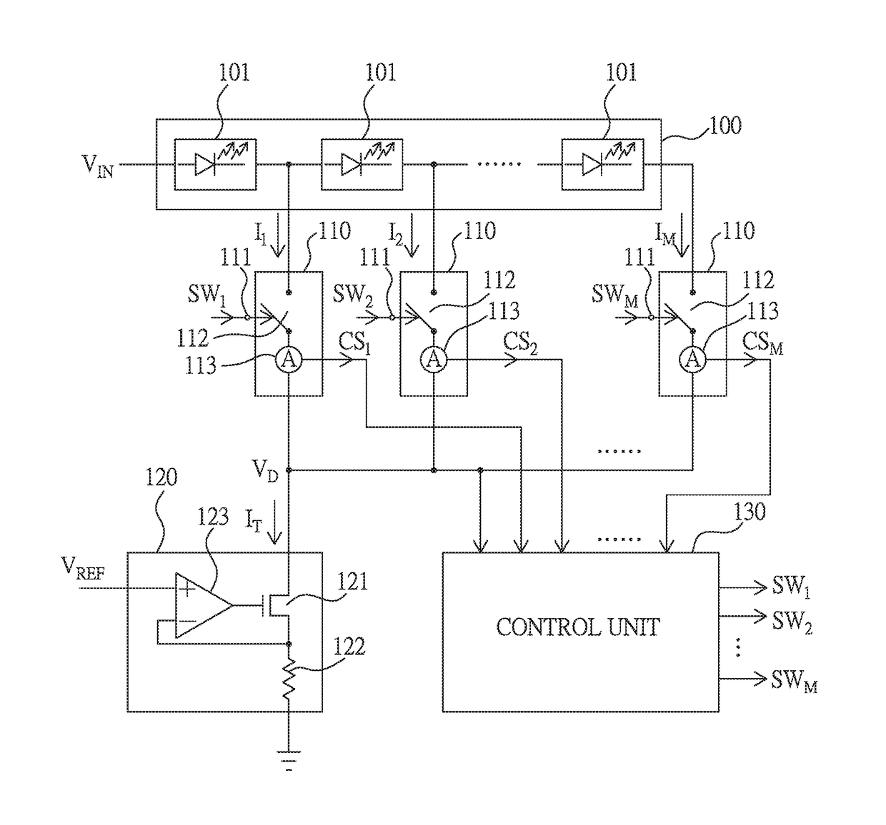
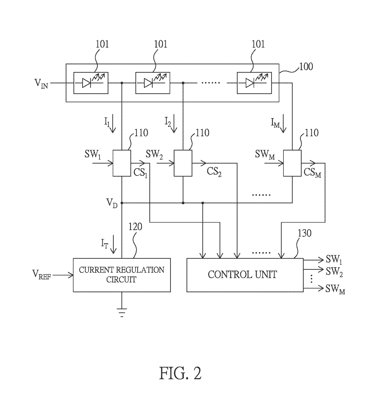
[0031]Please refer to FIG. 2, which illustrates a circuit diagram of a multi-stage LED driving circuit according to an embodiment of the present invention. As illustrated in FIG. 2, the multi-stage LED driving circuit includes an LED module 100, a plurality of switch units 110, a current regulation circuit 120, and a control unit 130.

[0032]The LED module 100 has a plurality of sub LED module 101, an input terminal, and a plurality of stage output terminals, wherein the sub LED module 101 has at least one LED, the input terminal is used for coupling with a line voltage VIN, the stage output terminals are coupled with the switch units 110, and the line voltage VIN can be a DC (direct current) voltage, a half-wave rectified voltage or a full-wave rectified voltage of an AC (alternating current) power, or a time varying voltage.

[0033]The switch units 110 are coupled with the stage output terminals so as to receive a plurality of branch currents I1-IM under the control of a plurality of ...


PUM


Abstract

A multi-stage LED driving circuit capable of eliminating current undershoot, including: an LED module having a plurality of stage output terminals; a plurality of switch units coupled with the stage output terminals to receive a plurality of branch currents and provide a plurality of current sensing signals; a current regulation circuit, having a control end coupled with a variable reference voltage, and a current path for receiving the branch currents; and a control unit, receiving the current sensing signals and a voltage signal at an input terminal of the current path, and controlling the switch units; wherein, the control unit uses every two adjacent signals of the current sensing signals to get a ratio in turn to determine whether to switch off a corresponding switch unit of the switch units after a deferred time, and uses the voltage signal to determine whether to change the deferred time.

Description

BACKGROUND OF THE INVENTION[0001]Field of the Invention[0002]The present invention relates to an LED (light emitting diode) driving circuit, especially to a multi-stage LED driving circuit capable of eliminating current undershoot.[0003]Description of the Related Art[0004]General multi-stage LED driving circuits are capable of providing a dynamic load having different numbers of LEDs for different levels of a line voltage, and operate in a way that a corresponding number of threshold voltages are predetermined according to stages of LEDs, and the number of LEDs included in the dynamic load is changed when the line voltage crosses one of the threshold voltages.[0005]However, as the current-voltage characteristic curves of the LEDs are likely different, therefore, the predetermined threshold voltages are not likely suitable for different samples of the LED module. In other words, as randomly selected LEDs tend to have different forward voltage drops under a same operation current, the...

Claims


Application Information

Patent Timeline
IPC IPC(8): H05B33/08H05B44/00
CPCH05B33/0887H05B33/0842H05B33/083H05B45/48
Inventor LAN, MAO-FENGLEE, TIEN-PAOPENG, HSIN-HEN
Owner LUXMILL ELECTRONICS
Why Eureka
Try Eureka