
Combustor for gas turbine engine

a gas turbine engine and combustion chamber technology, applied in the direction of machines/engines, combustion types, lighting and heating apparatus, etc., can solve the problem of particularly likely backfiring phenomenon, achieve low nox combustion, suppress backfiring phenomenon, and stable combustion

Active Publication Date: 2017-03-23
KAWASAKI HEAVY IND LTD +1
View PDF12 Cites 15 Cited by
  • Summary
  • Abstract
  • Description
  • Claims
  • Application Information

AI Technical Summary

Benefits of technology

The present invention provides a combustor for a gas turbine engine that prevents local high-temperature combustion and backfiring phenomenon, suppresses generation of NOx, and stable maintains flame. This is achieved by continuous and stable combustion at multiple points using a jet of fuel, which is deflected and mixed with air to prevent high temperature zones and backfiring. The combustor includes an air-flow rectifying mechanism to supply uniform air flow to the fuel injector for further suppression of NOx and backfiring. Additionally, the combustor may include a cleaning mechanism to prevent clogging of fuel injector nozzles with soot. The fuel injection annular portions have a hollow space to allow the fuel to flow in a circumferential direction, which is cooled by the fuel flow.

Problems solved by technology

However, in a gas turbine engine using a highly reactive fuel including hydrogen, the backfiring phenomenon is particularly likely to occur.

Method used


Image

  • Combustor for gas turbine engine
  • Combustor for gas turbine engine
  • Combustor for gas turbine engine

Examples


Embodiment Construction

[0038]Hereinafter, embodiments of the present invention will be described with reference to the drawings, but the present invention is not limited to the embodiments.

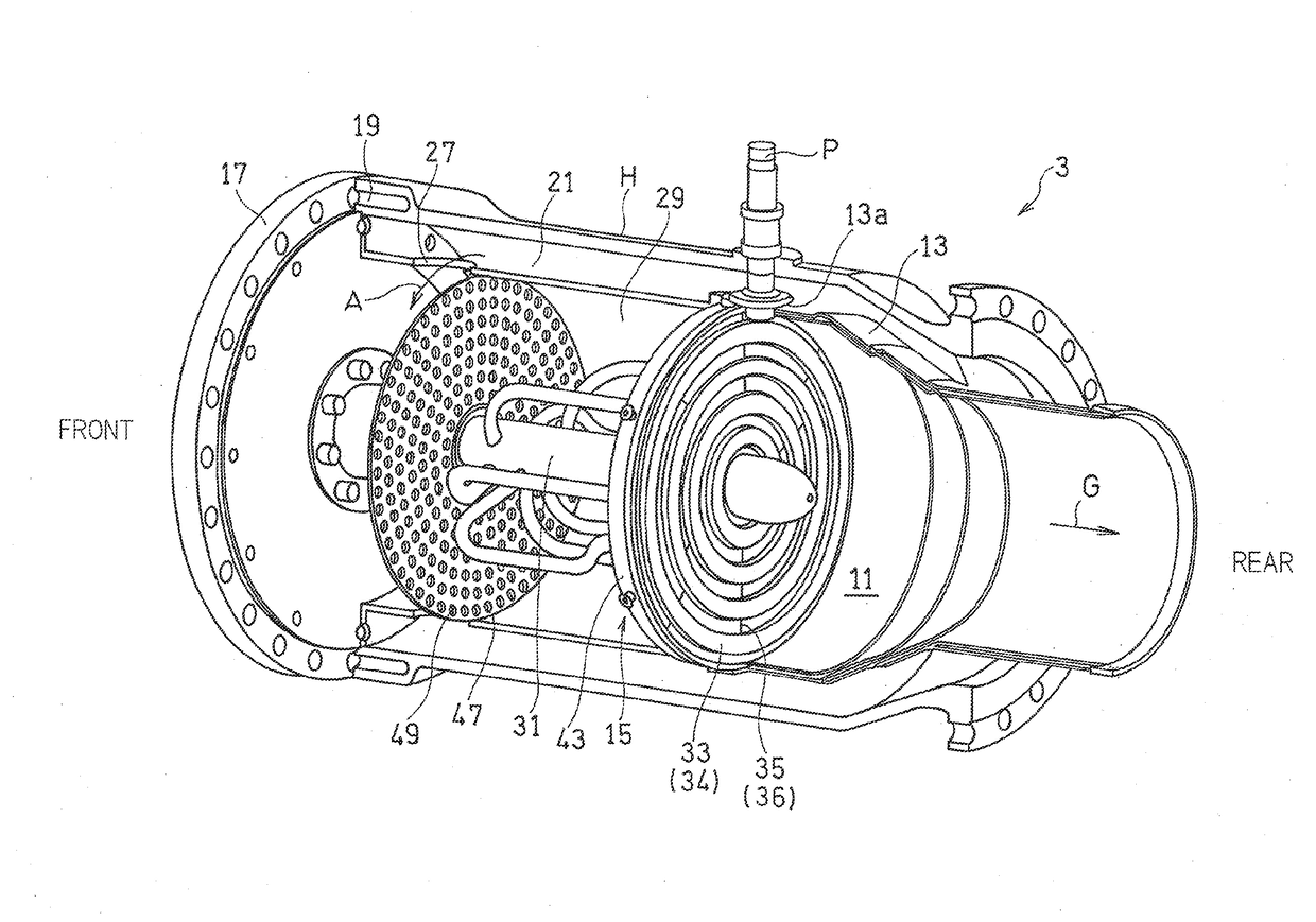
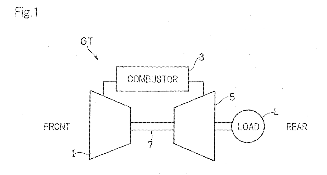
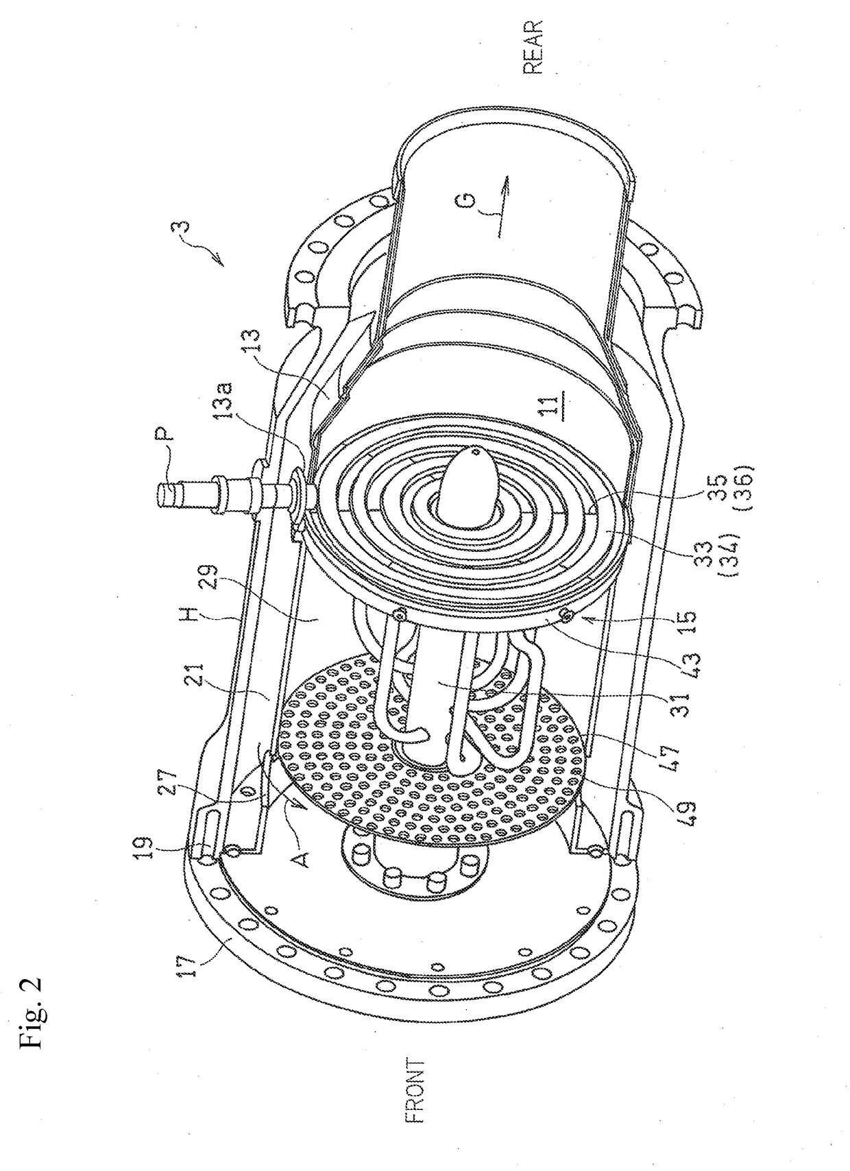
[0039]FIG. 1 shows a schematic configuration of a gas turbine engine (hereinafter referred to simply as a gas turbine) GT in which a combustor according to an embodiment of the present invention is applied. In the gas turbine GT, introduced air is compressed by a compressor 1 and guided to a combustor 3, and fuel is injected into the combustor 3. The fuel is combusted with the air, and the resulting high-temperature and high-pressure combustion gas drives a turbine 5. The turbine 5 is connected to the compressor 1 via a rotary shaft 7, and the compressor 1 is driven by the turbine 5. A load L such as a rotor of an aircraft or a generator is driven by an output of the gas turbine GT. In the present embodiment, hydrogen gas is used as the fuel injected into the combustor 3. In the following description, a side, in an axia...


PUM


Abstract

A combustor includes: a combustion liner having a combustion chamber formed therein; and a fuel injector mounted to a top portion of the combustion liner, and including a fuel injection member having a plurality of fuel injection annular portions and an air guide member including a plurality of combustion air annular portions that guide air for combustion. The fuel injection annular portions and the combustion air annular portions are arranged concentrically and alternately. The fuel injector injects fuel and air into the combustion chamber. Each of the fuel injection annular portions includes a plurality of fuel injection holes that are open in a radial direction thereof, and each of the combustion air annular portions includes a plurality of air guide grooves that are open in an axial direction thereof, and guide the air to the fuel jetted from the fuel injection holes.

Description

CROSS REFERENCE TO THE RELATED APPLICATION[0001]This application is a continuation application, under 35 U.S.C. §111(a), of international application No. PCT / JP2015 / 002714, filed May 28, 2015, which claims priority to Japanese patent application No. 2014-113268, filed May 30, 2014, the disclosure of which are incorporated by reference in their entirety into this application.BACKGROUND OF THE INVENTION[0002]Field of the Invention[0003]The present invention relates to combustors used in gas turbine engines.[0004]Description of Related Art[0005]For environment protection purposes, in gas turbine engines, strict environmental standards are set for the composition of emitted combustion exhaust gas. It is required to reduce harmful substances such as nitrogen oxide (hereinafter referred to as NOx) from the exhaust gas. Under such circumstances, in recent years, a combustion system adopting a premix combustion system which effectively reduces the amount of generated NOx, for example, a com...

Claims


Application Information

Patent Timeline
Patent Type & Authority Applications(United States)
IPC IPC(8): F23R3/28F02C7/22F23R3/16F23R3/00F23R3/10
CPCF23R3/286F23R3/002F23R3/10F05D2240/35F02C7/222F05D2220/32F23R3/16F23D14/70F23R3/18F23R3/34Y02T50/678F23C2900/9901
Inventor HORIKAWA, ATSUSHIKAZARI, MASAHIDEOKADA, KUNIOKITAJIMA, JUNICHIFUNKE, HARALDKUSTERER, KARSTENAYED, ANIS HAJ
Owner KAWASAKI HEAVY IND LTD
Learn More