Eureka AIR delivers breakthrough ideas for toughest innovation challenges, trusted by R&D personnel around the world.

System for radiography imaging and method of operating such system

a radiography imaging and system technology, applied in the field of radiography imaging systems, can solve the problems of posing a health risk to operators and other personnel, loss of productivity, loss of productivity,

Active Publication Date: 2017-03-23
GENERAL ELECTRIC CO
View PDF65 Cites 9 Cited by
  • Summary
  • Abstract
  • Description
  • Claims
  • Application Information

AI Technical Summary

Benefits of technology

The patent describes a radiography imaging system for generating images of a pipe assembly, which can be used in a pipe assembly manufacturing facility. The system includes a radiation source with a radioactive isotope and a detector. The detector includes an imaging plate and an imaging unit that generate images based on information from the imaging plate. The imaging unit has a pixel pitch of 25 to 100 microns. The system can be mounted on the pipe assembly and the neck of a welded pipe joint. The method involves illuminating the pipe assembly with the rays and generating an image within a short exposure time. The system can provide quick and accurate inspection of the pipe assembly during manufacturing.

Problems solved by technology

However, radiography imaging systems emit radiation that poses a health risk to operators and other personnel that may unnecessarily encounter the radiation.
However, evacuating the surrounding areas results in a loss of productivity.
However, moving the pipe assemblies also results in a loss of productivity.
Accordingly, moving and imaging four pipe assemblies at the remote site consumes twelve days.
Alternately, radiography imaging of the four pipe assemblies without relocating the pipe assemblies consumes only two days for all four assemblies.
Accordingly, moving the four pipe assemblies for radiography testing results in a ten day loss of productivity.

Method used


Image

  • System for radiography imaging and method of operating such system
  • System for radiography imaging and method of operating such system
  • System for radiography imaging and method of operating such system

Examples


Embodiment Construction

[0016]In the following specification and the claims, reference will be made to a number of terms, which shall be defined to have the following meanings.

[0017]The singular forms “a”, “an”, and “the” include plural references unless the context clearly dictates otherwise.

[0018]“Optional” or “optionally” means that the subsequently described event or circumstance may or may not occur, and that the description includes instances where the event occurs and instances where it does not.

[0019]Approximating language, as used herein throughout the specification and claims, may be applied to modify any quantitative representation that could permissibly vary without resulting in a change in the basic function to which it is related. Accordingly, a value modified by a term or terms, such as “about”, “approximately”, and “substantially”, are not to be limited to the precise value specified. In at least some instances, the approximating language may correspond to the precision of an instrument for...


PUM


Abstract

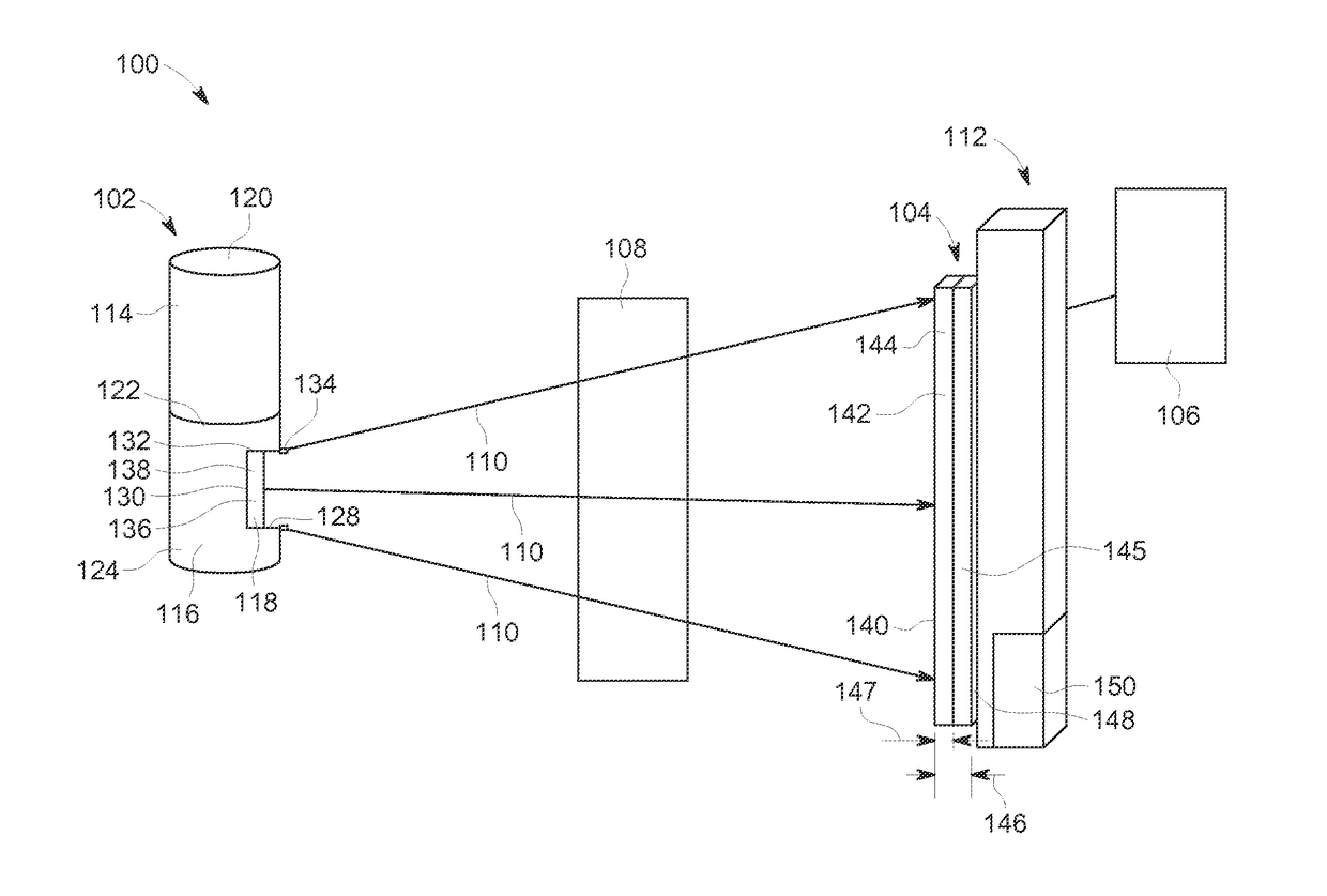
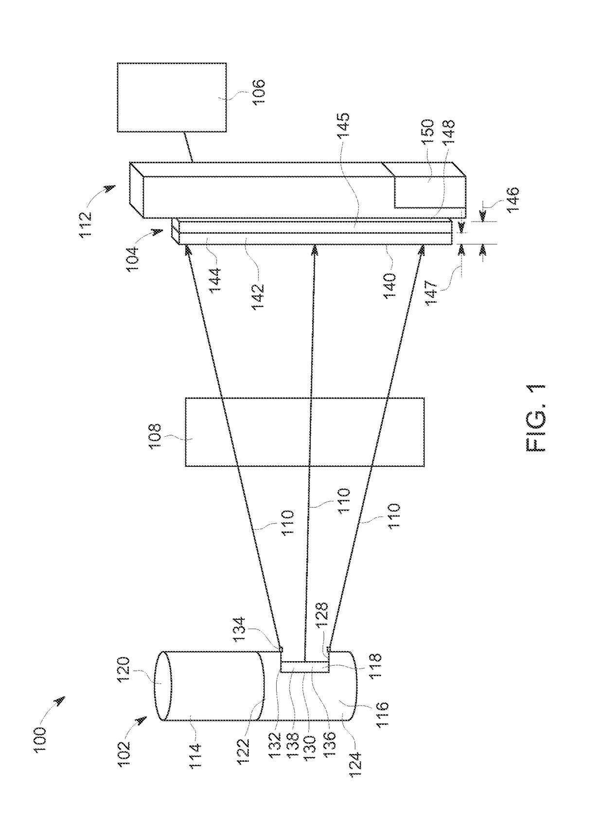
A radiography imaging system for generating images of a pipe assembly includes a radiation source for emitting rays. The pipe assembly includes at least one of a pipe, tubing, and a weld. The radiation source includes a radioactive isotope having an activity level within a range between about 1 Curie and about 40 Curies. The radiation source is positioned adjacent a portion of the pipe assembly. A detector is positioned opposite the radiation source. The portion of the pipe assembly is positioned between the radiation source and the detector such that the rays interact with the portion of the pipe assembly and strike the detector. The detector includes an imaging plate that is activated by illumination with the rays with an exposure within a range between about 0.5 Curie-minute and about 5 Curie-minutes of radiation. The imaging plate has a thickness within a range between about 5 mm and about 15 mm. The detector further includes an imaging unit for generating images based on information from the imaging plate. The imaging unit has a pixel pitch that is within a range between about 25 microns and about 100 microns.

Description

BACKGROUND[0001]The field of the disclosure relates generally to radiography imaging systems and, more particularly, to using a radiography imaging system to generate images of a pipe assembly.[0002]Radiography imaging systems use rays to image portions of a target. A radiation source of the radiography imaging systems emits the rays in a direction towards the target. Upon striking the target, some of the rays are absorbed by the target and some of the rays are scattered through interaction with the target. Some of the rays that are scattered by the target strike a sensor which is used to generate an image of the target. The resulting image shows internal portions of the target. Accordingly, radiography imaging is used to determine characteristics of the target that are incapable of determination by non-destructive visual inspection. However, radiography imaging systems emit radiation that poses a health risk to operators and other personnel that may unnecessarily encounter the radi...

Claims


Application Information

Patent Timeline
IPC IPC(8): G01N23/04
CPCG01N23/04G01N2223/401G01N2223/628G01T1/2012G01N23/083G01N23/087
Inventor BUENO, CLIFFORDGSCHWENDTNER, TAMASCHALMERS, GEORGE GIBSONFARQUHAR, DONALD SETONIBBA, ANTONIO LUIGI
Owner GENERAL ELECTRIC CO
Why Eureka
Eureka Blog
Learn More