Method and system for downhole object location and orientation determination

Active Publication Date: 2017-03-23
SILIXA
View PDF7 Cites 34 Cited by
  • Summary
  • Abstract
  • Description
  • Claims
  • Application Information

AI Technical Summary

Benefits of technology

[0011]Embodiments of the invention provide a downhole device that is intended to be co-located with an optical fiber, the location of which is to be found, for example by being fixed together in the same clamp. The device has an accelerometer or other suitable orientation determining means that is able to determine its positional orientation, with respect to gravity. A vibrator or other sounder is provided, that outputs the positional orientation information as a suitably encoded and modulated aco

Problems solved by technology

One issue with the use of perforating guns is to try and prevent the shaped charges from damaging any control or sensing cabling or other lines that may extend along the wellbore external of the casing.
As the perforating is performed as part of the well completion, by that point the fibers have typically already been cemented into the well bore, and hence repair can be very costly, or even impossible.
One problem with the above arrangement is one of cost, in that the metal rods are usually required to extend along a significant length of the well bore, hence increasing the material and production cost of the well.
In addition, the use of magnetometers to detect the rods is not particularly accurate, and particularly in some rock formations or in some regions where magnetic anomalies can occur that in

Method used


Image

  • Method and system for downhole object location and orientation determination
  • Method and system for downhole object location and orientation determination
  • Method and system for downhole object location and orientation determination

Examples


Embodiment Construction

[0057]A brief overview of embodiments of the invention will first be given, followed by a detailed description of particular embodiments.

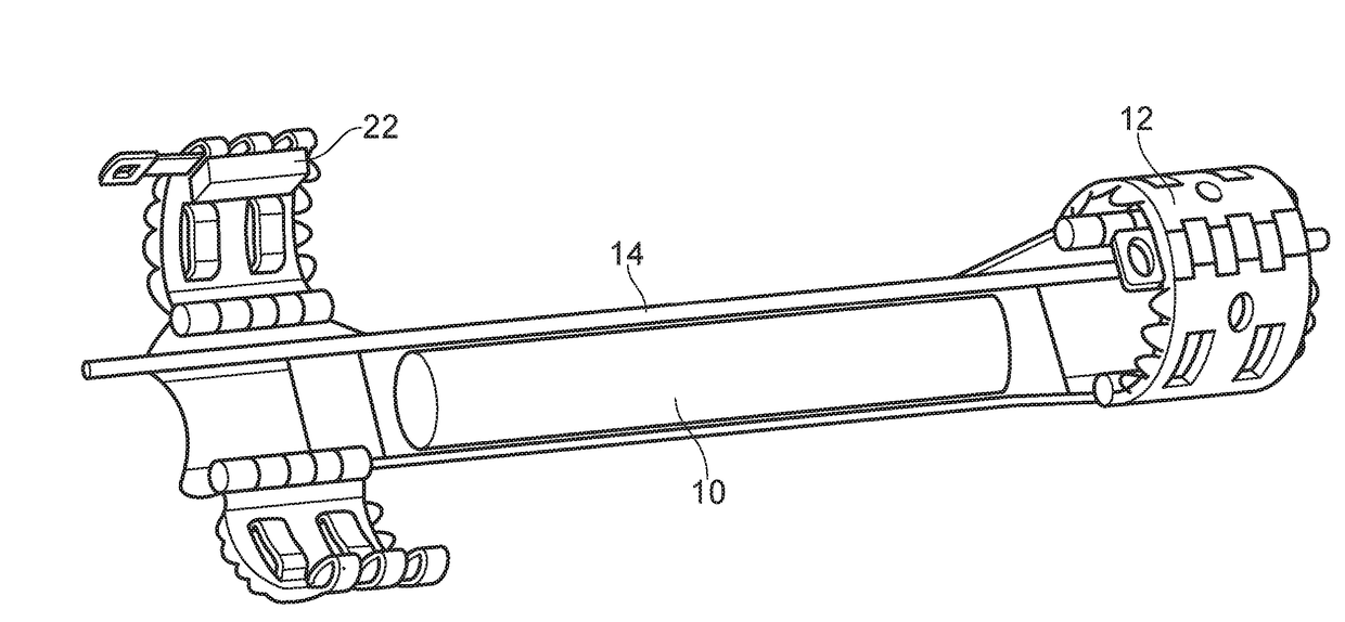
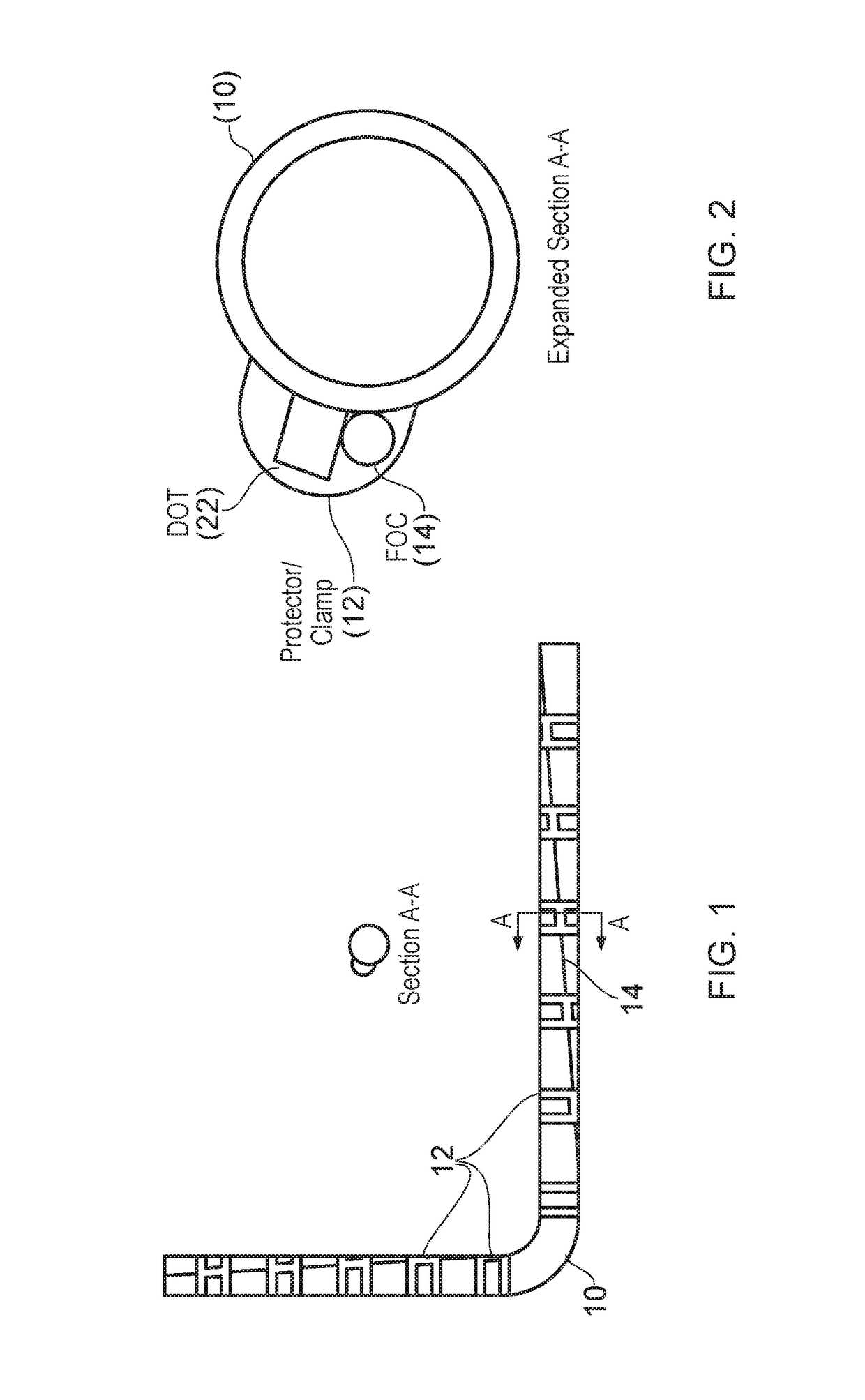
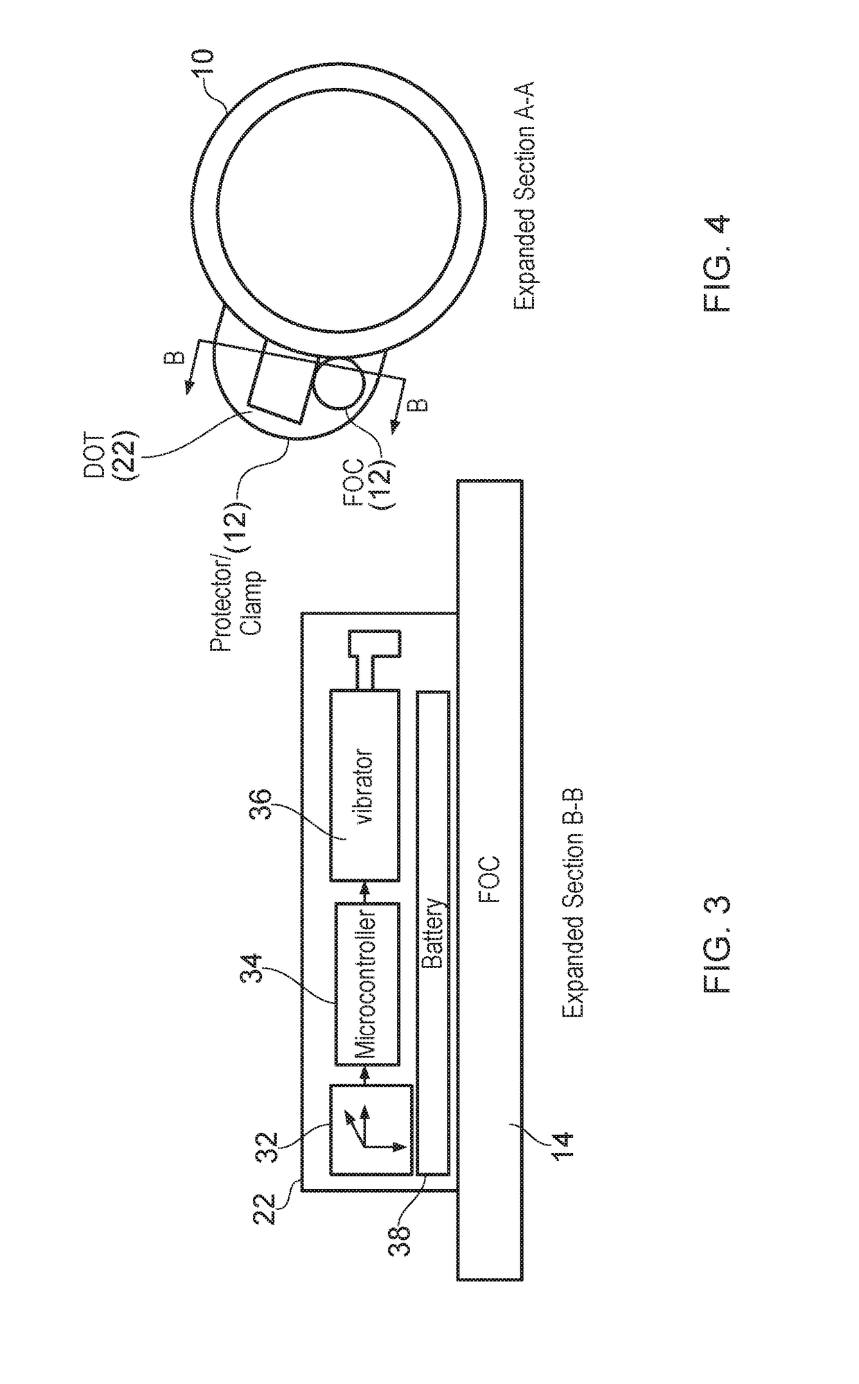
[0058]Fiber optic cables (FOC) installed on the outside of completion casing are at risk of being damaged during the perforation of the casing. To avoid damaging the FOC the perforation charges are azimuthally oriented away from the FOC. The azimuthal orientation of the FOC must be determined after installation of the FOC is complete. Traditional methods for determining the orientation of the FOC utilize instruments inside of the casing, typically conveyed on wireline, which detect the presence of the FOC on the outside of the casing using electromagnetic or ultrasonic measurements. To improve the reliability of detection using that method, wire rope, or other metallic mass, is installed parallel and adjacent to the FOC to increase the amount of metal mass to be detected at a minimum length equal to the interval to be perforated. This method for de...


PUM


Abstract

A downhole device is provided that is intended to be co-located with an optical fiber cable to be found, for example by being fixed together in the same clamp. The device has an accelerometer or other suitable orientation determining means that is able to determine its positional orientation, with respect to gravity. A vibrator or other sounder is provided, that outputs the positional orientation information as a suitable encoded and modulated acoustic signal. A fiber optic distributed acoustic sensor deployed in the vicinity of the downhole device detects the acoustic signal and transmits it back to the surface, where it is demodulated and decoded to obtain the positional orientation information. Given that the device is co-located with the optical fiber the position of the fiber can then be inferred. As explained above, detecting the fiber position is important during perforation operations, so that the fiber is not inadvertently damaged.

Description

TECHNICAL FIELD[0001]The present invention provides a method and system for determining the orientation and / or location of a downhole object, and in particular for example an object such as an optical fiber cable that is located on the exterior surface of production tubing and held on by a clamp. Particular embodiments provide for a co-located device with the optical fiber that is able to determine its own orientation and communicate the determined orientation back to the surface.BACKGROUND TO THE INVENTION AND PRIOR ART[0002]To detect an acoustic signal downhole, distributed acoustic sensing (DAS) is commonly and effectively used. This method employs fibre optic cables to provide distributed acoustic sensing whereby the fibre optic cable acts as a string of discrete acoustic sensors, and an optoelectronic device measures and processes the returning signal. The operation of such a device is described next.[0003]A pulse of light is sent into the optical fibre, and a small amount of l...

Claims


Application Information

Patent Timeline
IPC IPC(8): G01V1/46E21B47/09G01V1/22G01V11/00G01D5/14
CPCG01V1/46G01V11/002E21B43/116G01V1/226E21B47/091G01D5/14G01V1/44E21B47/0224E21B47/022G01V11/00E21B47/024G01C9/00E21B47/095
Inventor MILNE, CRAIGFRANKEY, BRIANPARKER, TOMFARHADIROUSHAN, MAHMOUD
Owner SILIXA
Why Eureka
Try Eureka