Optical connector for sterile applications

Active Publication Date: 2017-03-23
KONINKLJIJKE PHILIPS NV
View PDF2 Cites 14 Cited by
  • Summary
  • Abstract
  • Description
  • Claims
  • Application Information

AI Technical Summary

Benefits of technology

[0010]Such optical connector system is advantageous since it allows e.g. the first ferrule to be non-sterile, while the second ferrule is sterile, since the optical element serves as a sterility barrier, e.g. for connecting a sterile guidewire and a non-sterile patch cord. Still, the connector system can be manufactured in versions that allows medical back-loading procedures. The optical connector system is further advantageous since it is well suited for miniature applications, due to the low complexity and the possibility of implementation with few single components.
[0011]E.g. the optical connector system may be used to connect a guidewire that may

Problems solved by technology

During a medical procedure a sterility problem may arise in case the optical waveguide needs to be disconnected and the (now non-sterile) proximal end of the m

Method used


Image

  • Optical connector for sterile applications
  • Optical connector for sterile applications
  • Optical connector for sterile applications

Examples


Example

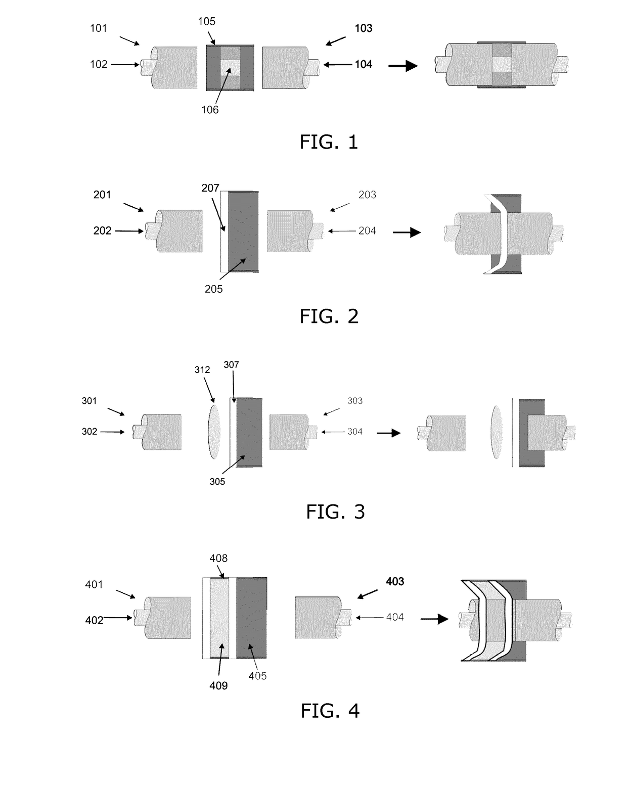
[0043]FIG. 1 illustrates a side section view of an optical connector system embodiment where a receptacle arrangement forms a connecting piece 105, 106 for connecting two ferrules 101, 103. To the left a sketch shows the system in a disconnected state, and to the right the system is shown in a connected state. First and second ferrules 101, 103 have respective first and second optical fibers 102, 104 arranged therein. The optical fibers 102, 104 may be multi-core optical fibers, and they reside in the center of the ferrules 101, 103. Ends of the ferrules 101, 103 are inserted from opposite ends of a receiving body 105 forming part of a receptacle arrangement. An optical element 106 in the form of a short optical waveguide, e.g. multi-core waveguide, is arranged inside the receiving body 105. The optical element 106 serves to provide an optical connection between the first and second optical fibers 102, 104 in a connected state, namely by forming an optical transmission path, or mult...


PUM


Abstract

An optical connector system for reversible optical connection between two optical fibers (102, 104) with their end parts inside respective ferrules. A receptacle arrangement has a receiving body (105) for receiving at least one of the ferrules (103). An optical element (106) of the receptacle arrangement serves to provide optical connection between the two optical fibers in a connected state of the optical connector system, and at the same time, the optical element (106) serves as a sterility barrier between the two optical fibers. The optical element (106) can be an optical waveguide, e.g. a piece of optical fiber similar to the two optical fibers (102, 104), and arranged within the receiving body (105). Alternatively, the optical element may be a thin flexible membrane (207, 307) which is optically transparent. As a further alternative, the optical element may be a sterilizing fluid (409) arranged inside a container that can be punctured upon insertion of one of the ferrules (401, 403) into the container (408), to allow an optical fiber end to be sterilized by the fluid (409) prior to entering into the connected state. In a further embodiment, an optical lens (312) is used to project light from one fiber end through a membrane (307) to the opposite fiber end.

Description

FIELD OF THE INVENTION[0001]The present invention relates to the field of connectors for optical fibers. More specifically, this invention relates to optical connections allowing connection and disconnection in a sterile zone.BACKGROUND OF THE INVENTION[0002]In minimally invasive medical interventions needles, guide wires, sheaths and catheters are inserted in the patient in order to find and measure, on the one hand, the relevant anatomy of the patient and treat or place a stent (for example) on the other hand. Clearly, the part of the devices inserted into the patient either must be sterile at all times or should only be contaminated with fluids and tissue from the patient itself. When a needle, guide wire or catheter is armed with a sensor or actuator, some connection (for example electrical wire or optical fiber) must be made to transmit the information or power to or from a controller or interrogator placed in the non-sterile zone, away from the patient. Somewhere along the tra...

Claims


Application Information

Patent Timeline
IPC IPC(8): G02B6/38A61B5/00
CPCG02B6/3866G02B6/3825G02B6/3871G02B6/3853A61B2562/228G02B6/3885A61B5/0084A61B2090/306G02B6/387
Inventor VAN DER MARK, MARTINUS BERNARDUSVAN PUTTEN, EIBERT GERJANEVENAAR-GEVEN, HENDRINA HELENA ALEIDAVERHOECKX, GODEFRIDUS JOHANNESVAN DEN BIJGAART, ADRIANUS WILHELMUS DIONISIUS MARIA
Owner KONINKLJIJKE PHILIPS NV
Why Eureka
Try Eureka