Laser machining robot

a laser machining robot and laser machining technology, applied in computer control, program control, instruments, etc., can solve problems such as interference with peripheral devices, and achieve the effect of reducing the number of cables and reducing the interference of cables disposed in the laser machining robot with peripheral devices

Active Publication Date: 2017-03-23
PANASONIC INTELLECTUAL PROPERTY MANAGEMENT CO LTD
View PDF10 Cites 5 Cited by
  • Summary
  • Abstract
  • Description
  • Claims
  • Application Information

AI Technical Summary

Benefits of technology

[0008]A laser machining robot of the present disclosure can reduce the number of cables disposed between the manipulator and the robot controller, so that the interference of the cables disposed in the laser machining robot with peripheral devices can be reduced.

Problems solved by technology

These cables can interfere with peripheral devices.

Method used


Image

  • Laser machining robot
  • Laser machining robot
  • Laser machining robot

Examples


Embodiment Construction

Exemplary Embodiment

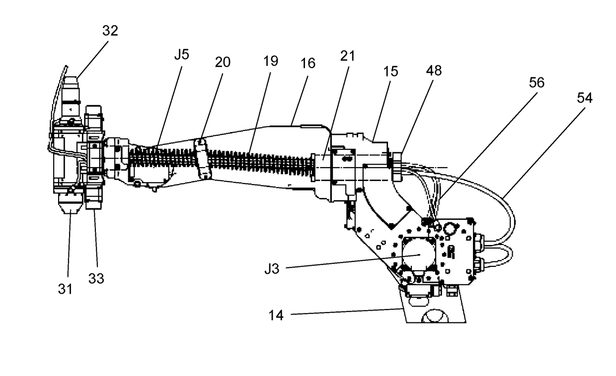
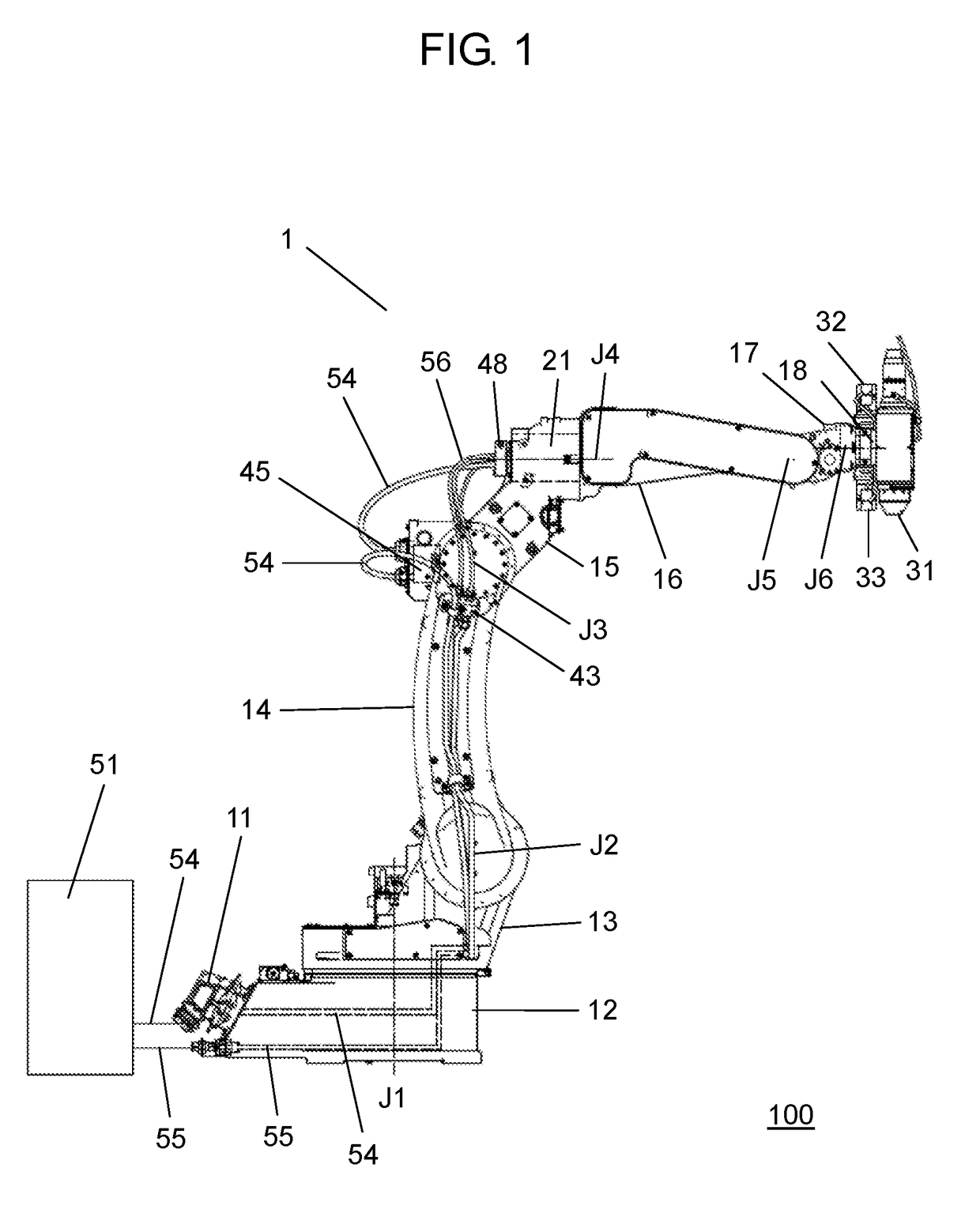
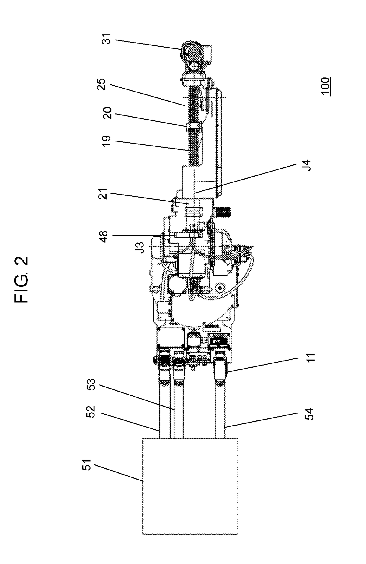
[0014]A description is provided for the exemplary embodiment of the present disclosure with reference to FIG. 1 through FIG. 5. FIG. 1 is a right side view of laser machining robot 100 that includes manipulator 1, robot controller 51, and laser machining head 31 in accordance with the exemplary embodiment. FIG. 2 is a top view of laser machining robot 100 that includes manipulator 1, robot controller 51, and laser machining head 31 in accordance with the exemplary embodiment. FIG. 3 is a left side view of a wrist of manipulator 1 in a state where laser machining head 31 is mounted in accordance with the exemplary embodiment. FIG. 4 is a perspective view showing the tip of the wrist of manipulator 1 in a state where laser machining head 31 is not mounted in accordance with the exemplary embodiment. FIG. 5 is a perspective view showing the tip of the wrist of manipulator 1 in a state where laser machining head 31 is mounted. Examples of laser machining robot 100 in...


PUM

PropertyMeasurementUnit
electric poweraaaaaaaaaa
diameteraaaaaaaaaa
Structureaaaaaaaaaa

Abstract

A laser machining robot includes a manipulator, a robot controller, and a laser machining head. The robot controller controls the operation of the manipulator. The laser machining head is mounted to the manipulator and scans a laser beam. The laser machining head includes a servomotor for driving a member for scanning the laser beam. The drive of the servomotor is controlled by the robot controller.

Description

TECHNICAL FIELD[0001]The present disclosure relates to a laser machining robot that has a laser machining head and a manipulator.BACKGROUND ART[0002]Patent Literature 1 describes a spot welding robot having a spot welding gun at the tip thereof. A first filament body and a second filament body are wired to the spot welding robot. As the first filament body, a power cable, a power supply line, and a signal line connected to a servomotor for driving the joint axis of the spot welding robot are grouped. As the second filament body, a power cable, a power supply line, and a signal line connected to the servomotor for driving the joint axis of the spot welding robot, and a welding power supply line connected to the spot welding gun, a cooling hose, a power supply line, and a signal line are grouped.[0003]The first filament body and the second filament body are connected from the connection hole in the base of the spot welding robot via the inside of the base, the side of the arm, and the...

Claims


Application Information

Patent Timeline
Patent Type & Authority Applications(United States)
IPC IPC(8): G05B19/402B23K26/08
CPCG05B19/402Y10S901/41G05B2219/36199B23K26/0884B25J19/0029
Inventor KUNG, YIHENGMUKAI, YASUSHITAKAHASHI, WATARU
Owner PANASONIC INTELLECTUAL PROPERTY MANAGEMENT CO LTD
Why Eureka
Try Eureka