RF filter

Inactive Publication Date: 2017-03-23
TONGYU TECH OY
View PDF2 Cites 4 Cited by
  • Summary
  • Abstract
  • Description
  • Claims
  • Application Information

AI Technical Summary

Benefits of technology

The invention provides a more integrated construction, easier manufacturing, and a more reliable connection between the resonator and other structures. This results in better control over frequency response.

Problems solved by technology

In prior art solutions the integral character of the construction has not been made advanced enough, and the parts modifying the frequency response of the filter are separate parts that must be attached to the resonator.

Method used


Image

  • RF filter
  • RF filter
  • RF filter

Examples


Embodiment Construction

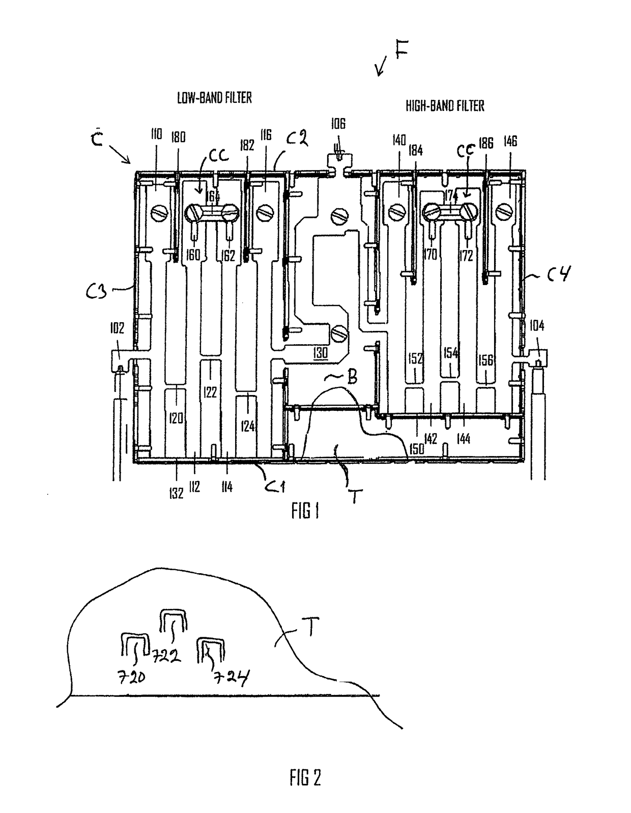
[0019]With reference to the figures, an RF filter F is disclosed, which filter F may be used in connection with or coupled to an RF device, such as a transmitter, a receiver, a transceiver or an amplifier. The RF device may be a radio unit in a cellular radio network or a module thereof, for example.

[0020]References 102 and 104 and 106 indicate transfer lines to which signal ports, such as coaxial connectors may be connected, the signal ports, in turn, may be connected to by means of cables that connect the filter F to an antenna and, for example, to a transceiver.

[0021]The filter F is a stripline type filter comprising strip-conductor-type resonators 110, 112, 114, 116 and strip-conductor-type resonators 140, 142, 144, 146, and a casing C with casing sides B, T and ends C1 to C4. A minimum of two resonators are provided. In the example of FIG. 1 the resonators are in two groups so that between the resonator groups 110, 112, 114, 116 and, on the other hand, 140, 142, 144, 146 there ...


PUM


Abstract

An RF filter, particularly a stripline type RF filter, includes a casing and two or more strip-conductor-type resonators in the casing. At a distance from the ends of the resonator, between the resonator sides, there are one or more coupling lines forming an integral piece with the resonators.

Description

CROSS-REFERENCE TO RELATED APPLICATIONS[0001]This application is a National Stage application of International Application No. PCT / F12015 / 050356, filed May 22, 2015, which claims benefit to Finnish Application No. FI 20145470, filed May 23, 2014, which are incorporated by reference herein in their entirety.BACKGROUND[0002]Field[0003]The invention relates to an RF filter.[0004]Description of the Related Art[0005]RF filters, i.e. radio frequency filters, are used in connection with RF devices, such as transmitters, receivers or transceivers, used in base stations of mobile phone networks, for example.[0006]Resonator type filters comprise a casing structure with one or more compartments whose shape is defined by the wall structure of the casing.[0007]Typically, a compartment of the casing structure may contain an inner conductor, referred to as a resonator or a resonator pin, attached to the bottom of the compartment or cavity, a common structure being a coaxial resonator in which the ...

Claims


Application Information

Patent Timeline
IPC IPC(8): H01P1/213H01P3/08
CPCH01P3/08H01P1/2135H01P1/20336H01P5/04H01P1/2039H01P1/205H01P7/088
Inventor NIIRANEN, ERKKI
Owner TONGYU TECH OY
Why Eureka
Try Eureka