Measuring Angle of Incidence in an Ultrawideband Communication System

a communication system and ultrawideband technology, applied in direction finders using radio waves, instruments, digital transmission, etc., can solve the problems of increasing the number of channels, increasing the cost of power consumption, and reducing the efficiency of rake filter implementations, so as to avoid unnecessary number proliferation.

Active Publication Date: 2017-03-23
DECAWAVE
View PDF2 Cites 19 Cited by
  • Summary
  • Abstract
  • Description
  • Claims
  • Application Information

AI Technical Summary

Problems solved by technology

Furthermore, it is of no relevance in such systems which specific voltage levels are selected to represent each of the logic states.
One particular problem in multi-path, spread-spectrum systems, including UWB, is channel-induced noise present in the received signal.
Unfortunately, in known implementations of the UWB receiver, improvements in performance usually come at the expense of power.
However, known rake filter implementations tend to consume significantly more power than other prior art techniques.
We submit that prior art techniques for performing both carrier recovery and timing recovery in the digital domain are less than optimum.
If d is relatively large then this would provide quite an accurate estimate of θ. On the other hand, if d is small the estimate turns out to be highly error prone.

Method used


Image

  • Measuring Angle of Incidence in an Ultrawideband Communication System
  • Measuring Angle of Incidence in an Ultrawideband Communication System
  • Measuring Angle of Incidence in an Ultrawideband Communication System

Examples


Embodiment Construction

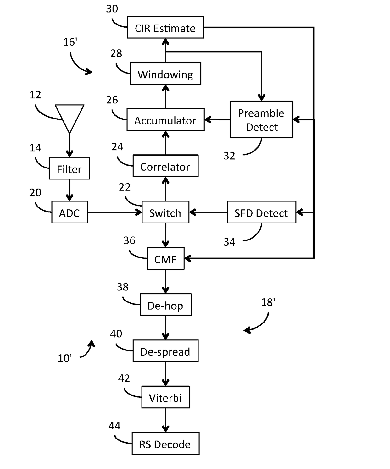
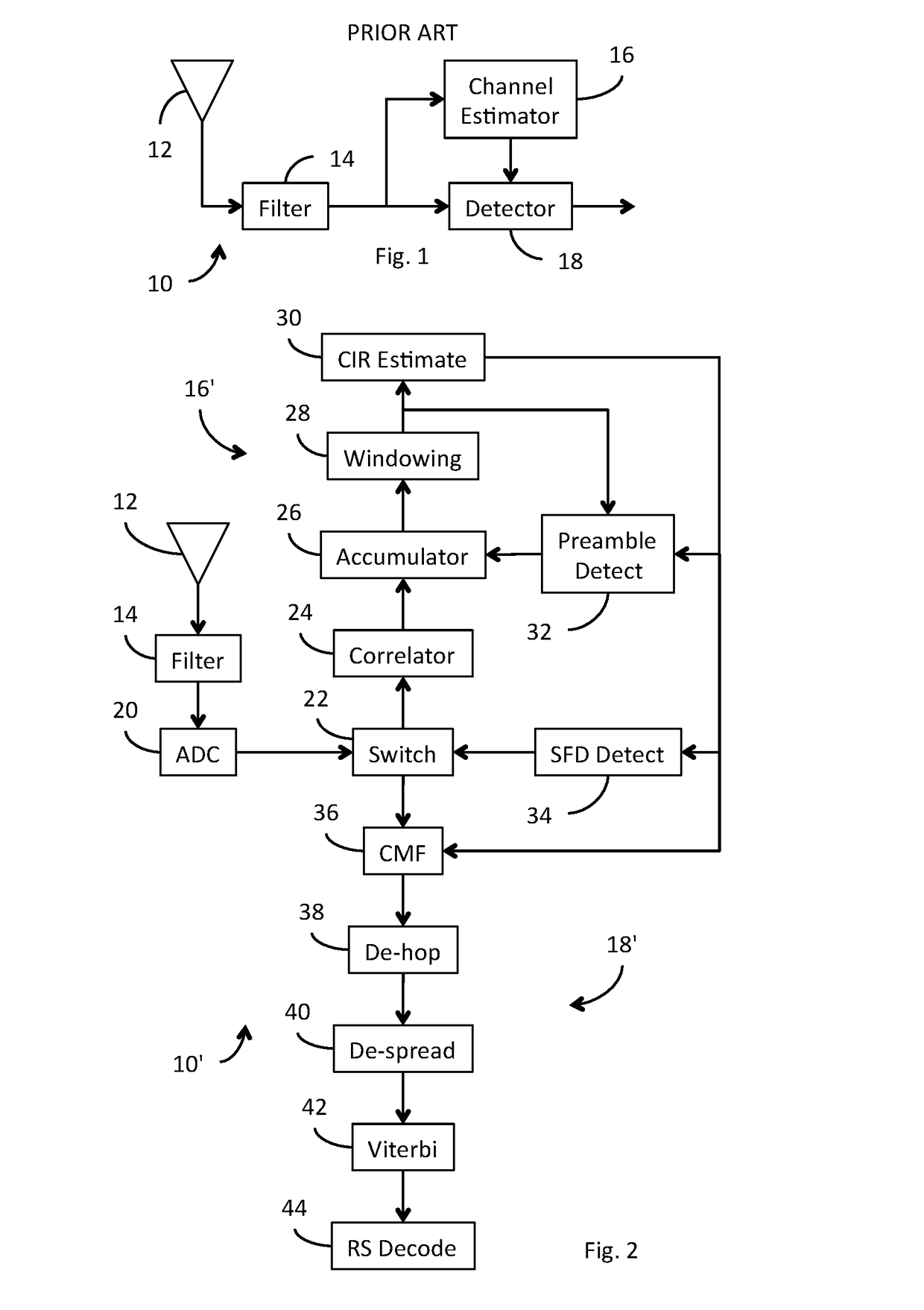
[0065]Shown in FIG. 2 is a UWB receiver 10′ constructed in accordance with our invention. As in the prior art system shown in FIG. 1, the signal received by antenna 12 is continuously conditioned by filter 14. The conditioned signal is then periodically sampled by an analog-to-digital converter (“ADC”) 20 and provided as a continuous series of digital samples. In accordance with a preferred embodiment of our invention, ADC 20 is specially adapted to provide each digital sample in ternary form, i.e., [−1, 0, +1]. In view of the difficulty of currently available standard digital circuit technology efficiently to represent a 3-value variable in the form of a single ternary trit, we anticipate, at least in the near term, such variables will require representation using 2 conventional, binary bits, wherein a first one of the bits represents the numeric component of the variable, i.e., [0, 1], and the second bit represents the sign of the variable, i.e., [+, −]. In this regard, it could b...


PUM


Abstract

In an ultra-wideband (“UWB”) receiver, a received UWB signal is periodically digitized as a series of ternary samples. During a carrier acquisition mode of operation, the samples are continuously correlated with a predetermined preamble sequence to develop a correlation value. When the value exceeds a predetermined threshold, indicating that the preamble sequence is being received, estimates of the channel impulse response (“CIR”) are developed. When a start-of-frame delimiter (“SFD”) is detected, the best CIR estimate is provided to a channel matched filter (“CMF”). During a data recovery mode of operation, the CMF filters channel-injected noise from the sample stream. Both carrier phase errors and data timing errors are continuously detected and corrected during both the carrier acquisition and data recovery modes of operation. The phase of the carrier can be determined by accumulating the correlator output before it is rotated by the carrier correction. By comparing the carrier phases of two receivers separated by a known distance, d, the angle of incidence, θ, of the signal can be determined.

Description

CROSS-REFERENCE TO RELATED APPLICATIONS[0001]This application is a Continuation-In-Part of PCT Application Serial No. PCT / EP2013 / 070851, filed 7 Oct. 2013 (“First Parent Application”).[0002]This application is also a Continuation-In-Part of application Ser. No. 13 / 775,282, filed 28 Mar. 2013 (“Second Parent Application”).[0003]The First Parent Application is a Continuation-In-Part of application Ser. No. 13 / 033,098, filed 23 Feb. 2011 (“Third Parent Application”), which is in turn related to Provisional Application Ser. No. 61 / 316,299, filed 22 Mar. 2010 (“Parent Provisional”).[0004]The Second Parent Application is also a Continuation-In-Part of Application Ser. No. 12 / 885,517, filed 19 Sep. 2010, now U.S. Pat. No. 8,437,432, issued 7 May 2013 (“Parent Patent”), which is in turn also related to the Parent Provisional.[0005]The subject matter of this Application is also related to the subject matter of PCT Application Serial No. PCT / EP2013 / 070851, filed 7 Oct. 2013 (“Related Applicat...

Claims


Application Information

Patent Timeline
Patent Type & Authority Applications(United States)
IPC IPC(8): H04B1/7163G01S3/02G01S3/46H04L7/033
CPCH04B1/71637G01S3/46G01S3/023H04L7/033G01S3/48
Inventor MARROW, GAVINMCLAUGHLIN, MICHAELMCELROY, CIARAN
Owner DECAWAVE
Why Eureka
Try Eureka