Driving mechanism

a technology of driving mechanism and drive shaft, which is applied in the direction of dynamo-electric machines, toothed gearings, windows, etc., can solve the problems of low transmission efficiency and inability to produce power

Active Publication Date: 2017-03-30
JOHNSON ELECTRIC SA
View PDF4 Cites 6 Cited by
  • Summary
  • Abstract
  • Description
  • Claims
  • Application Information

AI Technical Summary

Problems solved by technology

However, the motor directly drives the worm and gear transmission assemb

Method used


Image

  • Driving mechanism
  • Driving mechanism
  • Driving mechanism

Examples


Embodiment Construction

[0010]The technical solutions of the embodiments of the present disclosure will be clearly and completely described as follows with reference to the accompanying drawings. Apparently, the embodiments as described below are merely part of, rather than all, embodiments of the present disclosure. Based on the embodiments of the present disclosure, any other embodiment obtained by a person skilled in the art without paying any creative effort shall fall within the protection scope of the present disclosure.

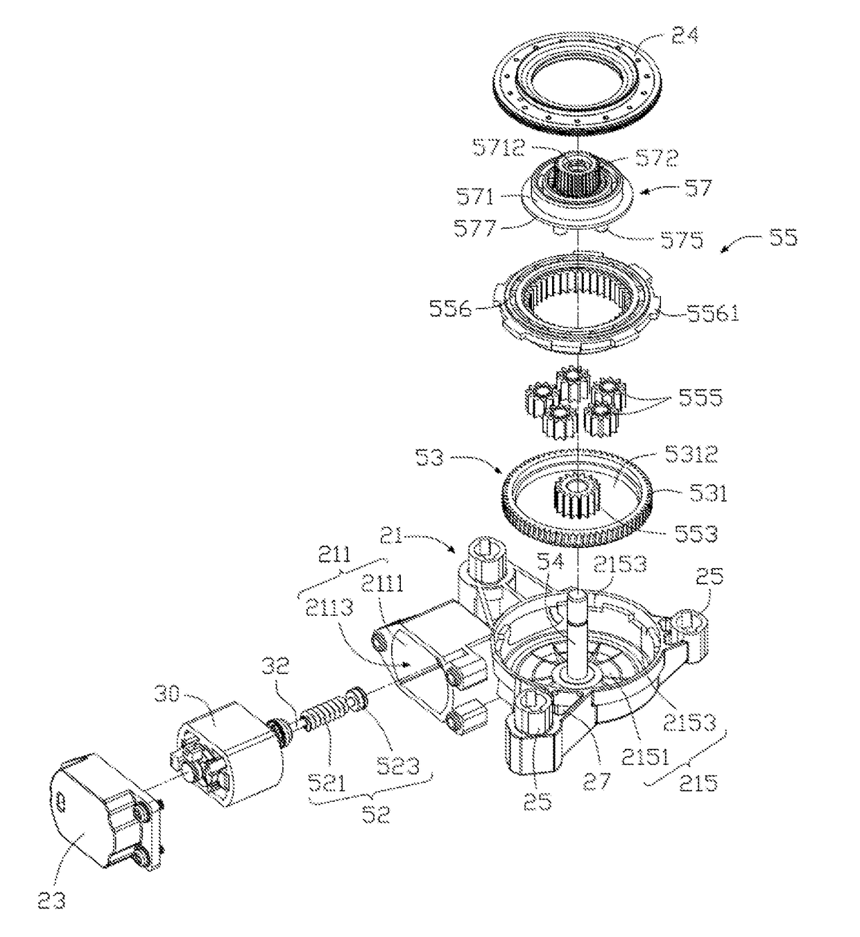
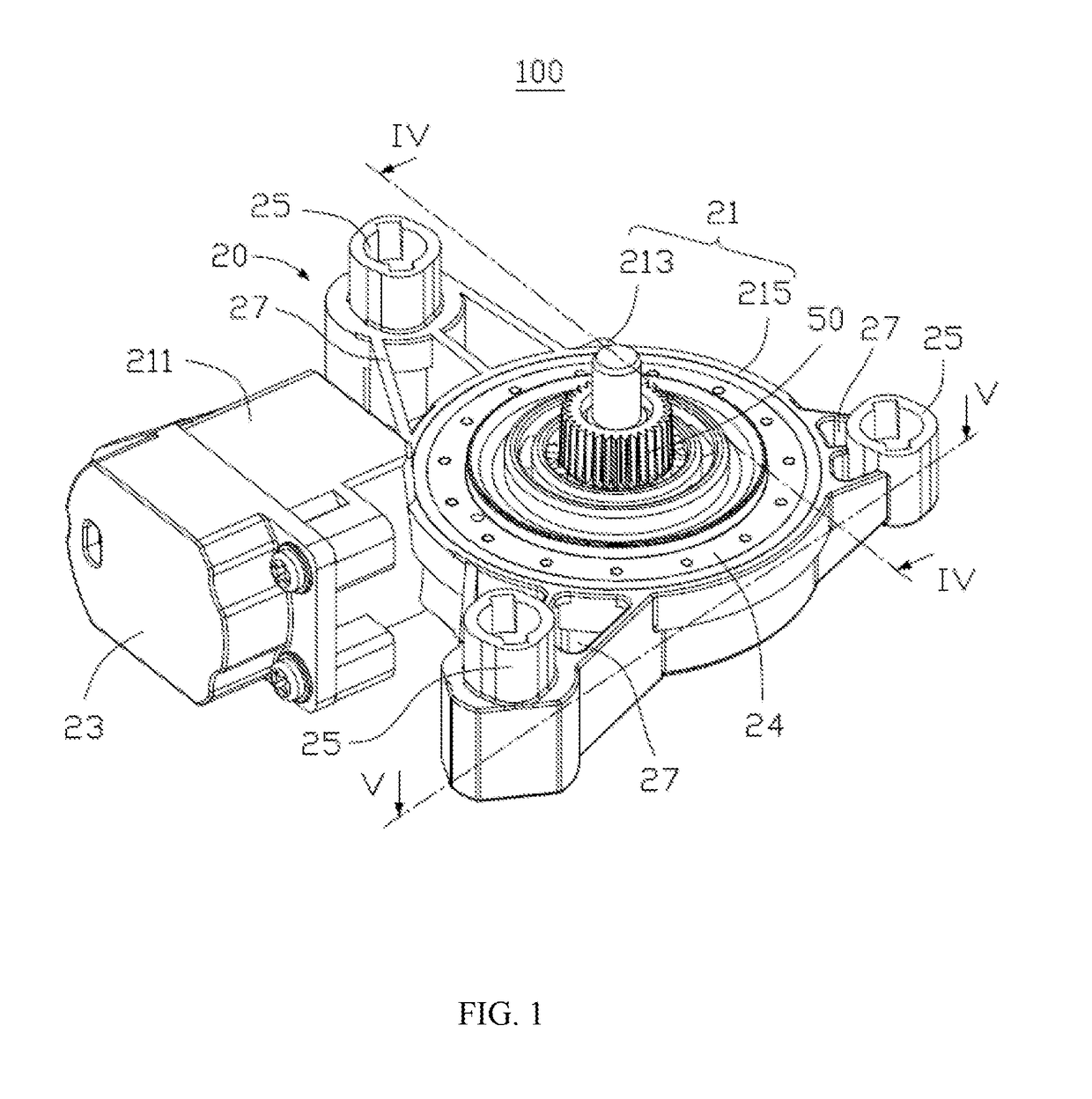
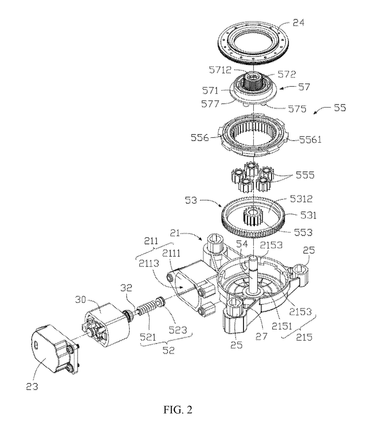
[0011]Referring to FIG. 1, a driving mechanism 100 in accordance with one embodiment of the present disclosure is used to drive an external device (not shown) to rotate or drive the external device to translate through a transmission mechanism (not shown). In the embodiment, the external device may be a vehicle window. By controlling the driving mechanism 100, the vehicle window can be driven to open or close. Alternatively, the external device may be another movable device such as a ...


PUM


Abstract

A driving mechanism drives a vehicle window to move up and down. The driving mechanism includes a housing, and a driving assembly and a transmission assembly. The driving assembly is engaged with the transmission assembly. The driving assembly is partially received in the housing. The transmission assembly includes a first transmission member connected to the driving assembly, a second transmission member engaging with the first transmission member, and a planetary gear set. The planetary gear set connects to an external device. The driving assembly drives the first transmission member which in turn drives the second transmission member to rotate. The second transmission member drives the planetary gear set which in turn drives the vehicle window to move.

Description

CROSS REFERENCE TO RELATED APPLICATIONS[0001]This non-provisional patent application claims priority under 35 U.S.C. §119(a) from Patent Application No. 201510642609.3 filed in the People's Republic of China on Sep. 30, 2015; and from Patent Application No. 201510998632.6 filed in the People's Republic of China on Dec. 25, 2015.FIELD OF THE INVENTION[0002]The present disclosure relates to a driving mechanism.BACKGROUND OF THE INVENTION[0003]A vehicle window is usually driven by a driving mechanism to open and close. The driving mechanism generally includes a housing, a motor and a speed reduction transmission assembly disposed in the housing. The motor drives the vehicle window to open or close through the transmission assembly. The speed reduction transmission assembly is a worm and gear transmission assembly. However, the motor directly drives the worm and gear transmission assembly, which leads to unstable power output and low transmission efficiency.BRIEF DESCRIPTION OF THE DRAW...

Claims


Application Information

Patent Timeline
IPC IPC(8): E05F15/697F16H1/16F16H1/28H02K21/12H02K1/27H02K1/12H02K7/116F16H37/04F16H57/039
CPCE05F15/697F16H37/041F16H1/16F16H1/28F16H57/039H02K1/2706F16H2057/02034H02K7/1166H02K21/12E05Y2201/434E05Y2201/72E05Y2900/55H02K1/12B60J1/17E05Y2201/702E05Y2201/704E05F15/689H02K1/146H02K1/278H02K29/00H02K2213/03H02K1/2753H02K7/14H02K21/14
Inventor LI, YUETA, JING NINGZHAO, YONG JUNLI, QIU MEIZHOU, CHUI YOUWANG, YONGLI, YONG
Owner JOHNSON ELECTRIC SA
Why Eureka
Try Eureka