Engine control apparatus

Inactive Publication Date: 2017-03-30
DENSO CORP
View PDF15 Cites 1 Cited by
  • Summary
  • Abstract
  • Description
  • Claims
  • Application Information

AI Technical Summary

Benefits of technology

[0028]The given threshold value is set to the minimum value of the range in which the pulsation parameter is permitted to change in the preselected period of time after the engine starter starts cranking the

Problems solved by technology

The inventor of this application has faced a drawback in that when the reference speed is fixed, the noise which arises while the speed of a crankshaft of the engine is being elevated by cranking of the engine may increase.
The greater the pulsating component of the engine speed, the greater a degree of torque acting the ring gear and the pinion gear will be, which will lead to mechanical noise.
This causes a great degree of torque to act on a contact between the pinion gear and the ring gear and also may result in relative bouncing of the pinion gear and the ring gear, thereby generating the mechanical noise arising from collision between the ring gear and the pinion gear.
In a high-s

Method used


Image

  • Engine control apparatus
  • Engine control apparatus
  • Engine control apparatus

Examples


Example

[0048]The first embodiment in which an engine control apparatus is used with a vehicle, such as an automobile, equipped with a multi-cylinder four-cycle engine (e.g., a four-cylinder four-cycle engine) working as a main power source will be described below with reference to the drawings.

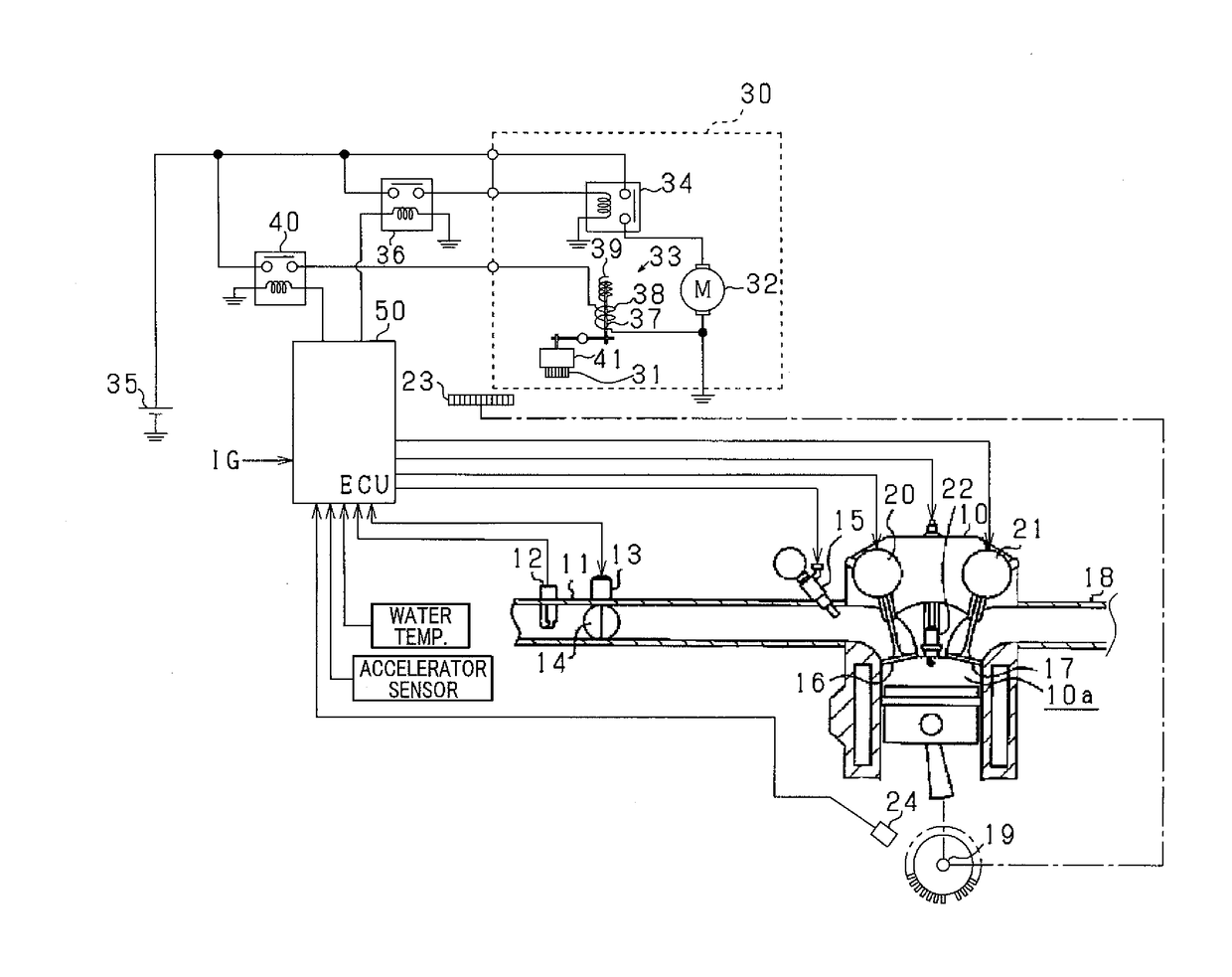
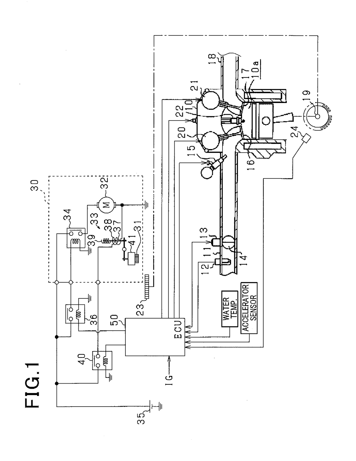
[0049]The vehicle is, as illustrated in FIG. 1, equipped with an engine 10, a starter 30 (which will also be referred to below as an engine starter), and an ECU (Electronic Control Unit) 50 working as the engine control apparatus. The engine 10 in this embodiment is a spark-ignited gasoline internal combustion engine. The engine 10 has an intake passage 11 in which an air flow meter 12 is installed. The air flow meter 12 works as an intake airflow sensor to measure the amount of intake air per unit time. The intake passage 11 has also installed therein a throttle valve 14 which is located downstream of the air flow meter 12 and driven by a throttle actuator 13 to regulate an area of a flow path in th...

Example

Second Embodiment

[0080]The second embodiment will be described below with respect to differences between itself and the first embodiment. The ECU 50 of this embodiment is designed to change, that is, determine the cranking terminating time as a function of the pulsating component contained in the speed of the engine 10 instead of the air intake quantity Gr.

[0081]FIG. 7 is a flowchart of a sequence of logical steps in a start control program executed by the ECU 50 in the second embodiment. The same step numbers, as employed in FIG. 2, will refer to the same operations, and explanation thereof in detail will be omitted here.

[0082]After step S14 wherein the starter 30 is turned on, the routine proceeds to step S22 wherein an amplitude ΔN of the pulsating component contained in the engine speed NE is calculated. The amplitude ΔN of the pulsating component may be, as can be seen in FIG. 6(a), derived by a difference between a minimum value N1 and a maximum value N2 of the engine speed NE...

Example

Third Embodiment

[0085]The third embodiment will be described below with respect to differences between itself and the first embodiment. The ECU 50 of this embodiment is designed to deactivate the starter 30 to terminate the cranking operation after the air-fuel mixture has been ignited in the combustion chamber 10a when the pulsating component contained in the speed of the engine 10 is great.

[0086]FIG. 8 is a flowchart of a sequence of logical steps in a start control program executed by the ECU 50 in the third embodiment. The same step numbers, as employed in FIG. 2, will refer to the same operations, and explanation thereof in detail will be omitted here.

[0087]After step S14 wherein the starter 30 is turned on, the routine proceeds to step S24 wherein it is determined whether the engine speed NE is higher than or equal to the intermediate speed Nmin, as already explained in the first embodiment. The ECU 50 works as a sub-determiner to execute the operation in step S24. The interme...


PUM


Abstract

An engine control apparatus is used with a system equipped with an engine and an engine starter. The engine starter includes an electrical motor, a pinion gear driven by the electrical motor, and a pinion shifter which thrusts the pinion to a location where the pinion is engageable with a ring gear coupled to the engine. The engine control apparatus determines a pulsation parameter which represents a pulsating component of speed of the engine or a value correlating with the pulsating component. The engine control apparatus works to thrust the pinion through the pinion shifter to establish engagement with the ring gear and then rotate the electrical motor to crank the engine. The engine control apparatus alters a cranking terminating time as a function of the pulsation parameter. This minimizes mechanical noise occurring between the pinion gear and the ring gear at the start of the engine.

Description

CROSS REFERENCE TO RELATED DOCUMENT[0001]The present application claims the benefit of priority of Japanese Patent Application No. 2015-191491 filed on Sep. 29, 2015, the disclosure of which is incorporated herein by reference.BACKGROUND[0002]1 Technical Field[0003]This disclosure relates generally to an engine control apparatus for use in a system equipped with an engine and an engine starter which includes an electric motor and a pinion gear to which torque, as produced by the electric motor, is transmitted for starting the engine.[0004]2 Background Art[0005]For instance, Japanese Patent First Publication No. 2002-188549 teaches an engine control apparatus designed to reduce mechanical noise occurring upon start of an internal combustion engine. The engine control apparatus works to increase the speed of the engine up to a given reference speed and then ignite fuel in the engine to start the engine. The reference speed is fixed to a value higher than a minimum value of a speed ran...

Claims


Application Information

Patent Timeline
IPC IPC(8): F02N11/08F02D13/02F02D9/02
CPCF02N11/0848F02D13/0234F02D9/02F02N11/0851F02D41/0002F02D41/062F02D2041/001F02N15/04F02N2200/022F02N11/087F02N11/106F02N15/067F02N19/004F02N2200/02Y02T10/12Y02T10/40
Inventor FUJITA, TATSUYA
Owner DENSO CORP
Why Eureka
Try Eureka