Radar device, signal processing device for radar device, and signal processing method

a signal processing and radar technology, applied in measurement devices, using reradiation, instruments, etc., can solve the problems of inability to accurately obtain distances, inability to accurately determine the frequency of peaks with respect to a plurality of targets, etc., to achieve the effect of improving the accuracy of distance measurement on individual targets

Active Publication Date: 2017-04-06
FUJISTU TEN
View PDF2 Cites 7 Cited by
  • Summary
  • Abstract
  • Description
  • Claims
  • Application Information

AI Technical Summary

Benefits of technology

[0007]It is therefore an object of the present invention to improve the accuracy of distance measurement on individual targets even in a case where there is a plurality of targets having distance differences corresponding to about 1 bin in the frequency spectrum.
[0009]According to the radar device, it is possible to improve the accuracy of distance measurement on individual targets even in a case where there is a plurality of targets having distance differences corresponding to about 1 bin in the frequency spectrum.

Problems solved by technology

However, in the related art as described above, even though it is possible to obtain the angles of individual targets by angle calculation, in a case where there is a plurality of targets having distance differences corresponding to about 1 bin in the frequency spectrum, it may be determined that the targets are equidistant from the radar device, and it may be impossible to accurately obtain their distances.
The reason is that, in a case where a radar device receives the reflected waves from a plurality of targets, there is a possibility that it may be impossible to sufficiently accurately determine the frequencies of peaks with respect to a plurality of targets having distance differences corresponding to about 1 bin in the frequency spectrum.

Method used


Image

  • Radar device, signal processing device for radar device, and signal processing method
  • Radar device, signal processing device for radar device, and signal processing method
  • Radar device, signal processing device for radar device, and signal processing method

Examples


first embodiment

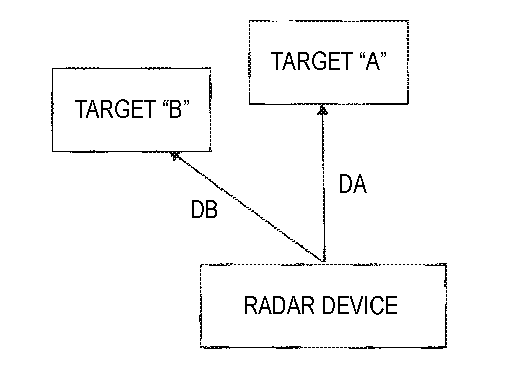
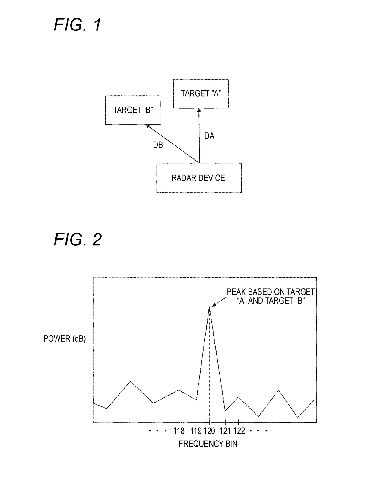
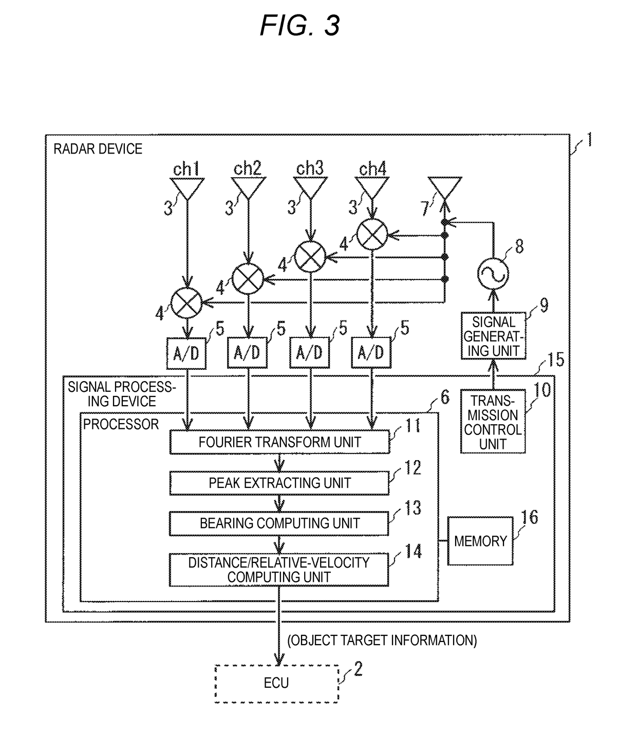
[0028]FIG. 3 is a view illustrating the configuration of a radar device 1 according to the present embodiment. The radar device 1 is mounted on a vehicle, and monitors the surroundings of the vehicle, and detects targets such as other vehicles and obstacles. The target detection results are output to an electrical control unit (ECU) 2 for controlling the vehicle, and are used for some purposes such as control on the vehicle. However, the radar device according to the present embodiment can also be used for various other uses (such as monitoring of flying aircrafts and sailing vessels) other than for a vehicle.

[0029]The radar device 1 includes: receiving antennae 3 (ch1 to ch4) arranged at regular intervals; mixers 4 (ch1 to ch4) connected to the receiving antennae 3, respectively; A / D (Analog to Digital) converters 5 (ch1 to ch4) connected to the mixers 4, respectively; and a signal processing device 15 including a processor 6 configured to process data of the A / D converters 5. Also...

second embodiment

[0060]In the first embodiment, in the FM-CW type radar device 1, in a case where the spectrum obtained by angle calculation includes a plurality of peaks, the processor 6 performs angle calculation with respect to a plurality of neighborhood frequency bins of the frequency bin of each peak. Thereafter, with respect to the angle in the arrival direction of each reflected wave obtained by angle calculation, the processor 6 determines a frequency having the highest power, and determines the distance and relative velocity between the vehicle and a corresponding target. However, implementation of the present invention is not limited to the FM-CW system. In other words, the present invention can be applied to other devices such as an FCM (Fast Chirp Modulation) type radar device.

[0061]When the waveform of one period of a transmission wave in which the frequency varies like a saw-tooth wave is defined as one chirp, the FCM system transmits a plurality of chirps with a period shorter than t...


PUM


Abstract

There is provided a radar device. A Fourier transform unit decomposes each of respective beat signals into a plurality of frequency components. A bearing computing unit specifies arrival angles of reflected-wave signals based on peak frequency components included in the plurality of frequency components, and calculates the signal intensities of arrival angle components of the reflected waves with respect to a plurality of neighborhood frequency components of the peak frequency components when the plurality of arrival angles of the reflected-wave signals are specified. A calculating unit selects one frequency component having the highest signal intensity from among the plurality of neighborhood frequency components, with respect to each of the arrival angles specified at a plurality of frequencies, and computes a distance between the radar device and a target on the basis of the one frequency component selected with respect to each of the arrival angles.

Description

TECHNICAL FIELD[0001]The present invention relates to a radar device, a signal processing device for the radar device, and a signal processing method.RELATED ART[0002]Radar devices of the related art use, for example, a frequency-modulated continuous-wave (FMCM) system. In a case where a radar device computes a distance to a measurement object (hereinafter, referred to as a target), using modulation of, for example, the FMCW system, the radar device performs fast Fourier transform (FFT) on beat signals which are mixtures of a transmission wave with the reflected waves from the target, and detects a peak of the frequency spectrum. Subsequently, on the basis of the frequency of the peak, the radar device obtains the distance from the radar device to the target. Further, the radar device performs angle calculation on the basis of reception signals obtained from a plurality of receiving antennae, respectively, thereby specifying the arrival angles of the reflected waves. In this way, th...

Claims


Application Information

Patent Timeline
Patent Type & Authority Applications(United States)
IPC IPC(8): G01S13/34G01S7/35G01S13/42G01S13/931
CPCG01S13/34G01S2007/356G01S7/352G01S13/42G01S13/345G01S13/931G01S7/356
Inventor OKAMOTO, TAKAYUKI
Owner FUJISTU TEN
Why Eureka
Try Eureka