Eureka AIR delivers breakthrough ideas for toughest innovation challenges, trusted by R&D personnel around the world.

Fuel cell anode catalyst and manufacturing method therefor

a fuel cell anode and catalyst technology, applied in the manufacture of final products, cell components, electrochemical generators, etc., can solve the problems of non-patent references and inadequate co tolerance of ptru/c catalysts, and achieve enhanced co tolerance and enhanced co tolerance

Inactive Publication Date: 2017-04-06
NATIONAL UNIVERSITY
View PDF3 Cites 0 Cited by
  • Summary
  • Abstract
  • Description
  • Claims
  • Application Information

AI Technical Summary

Benefits of technology

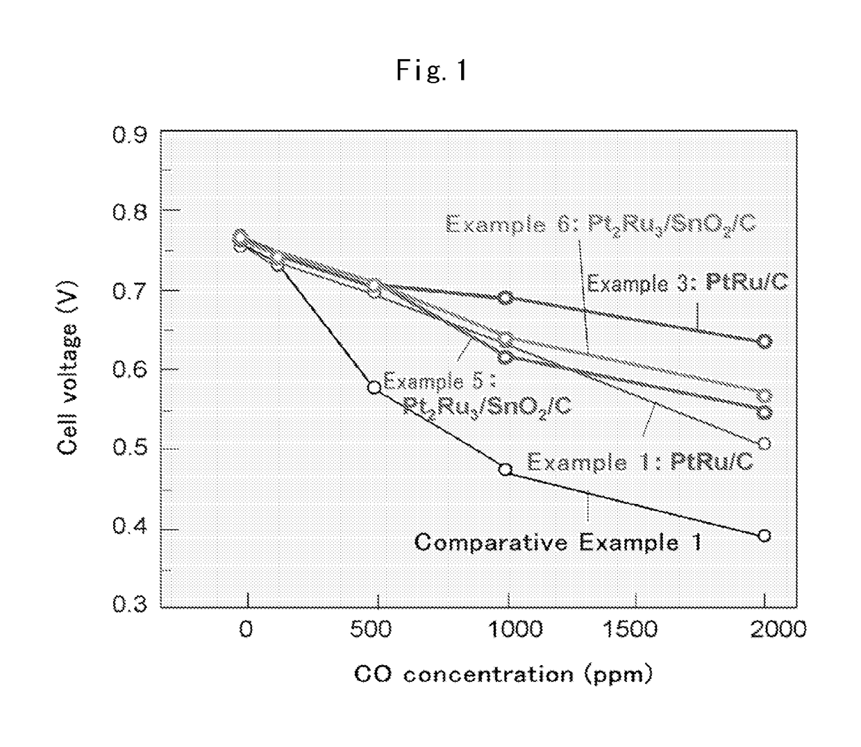
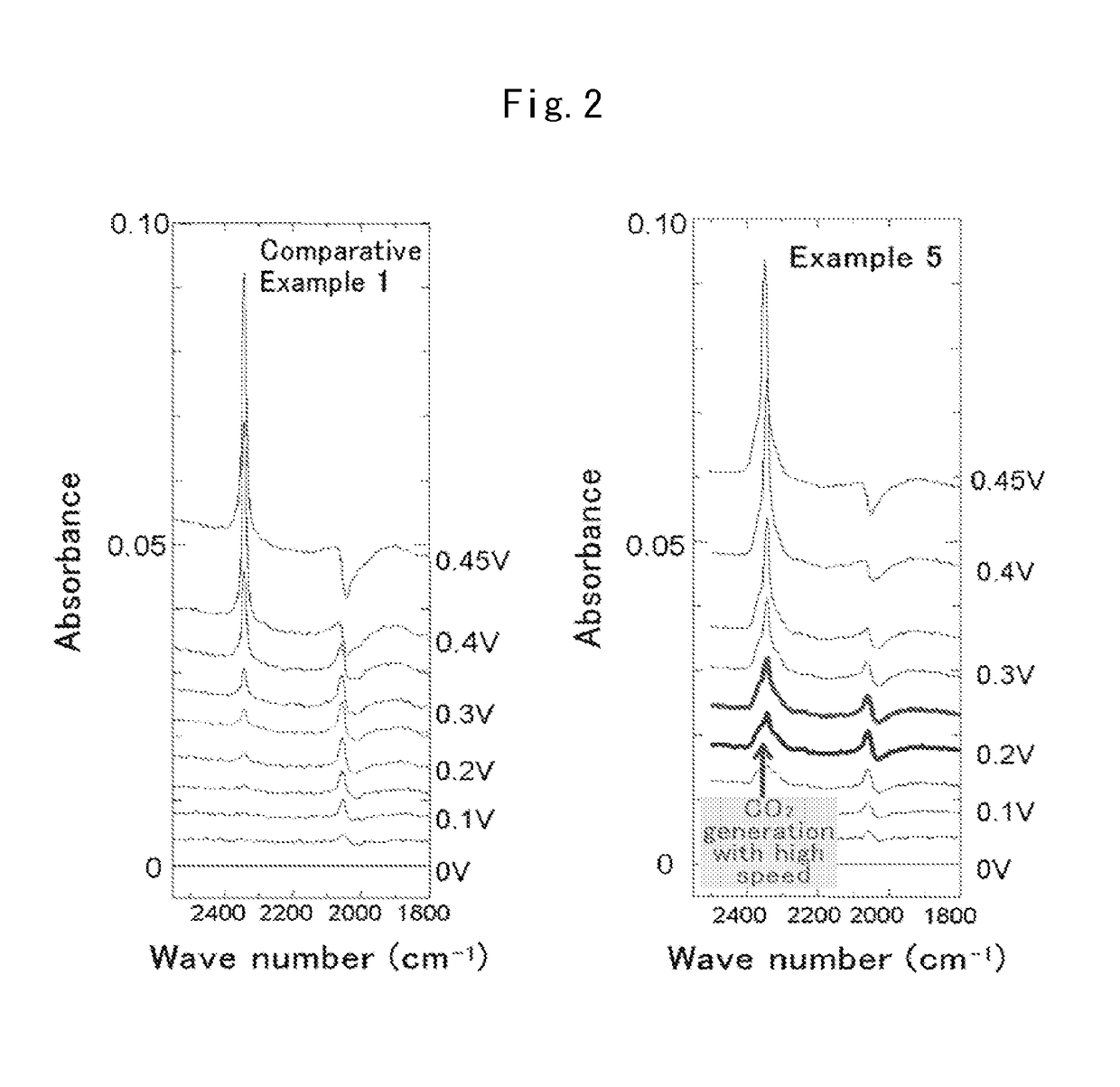
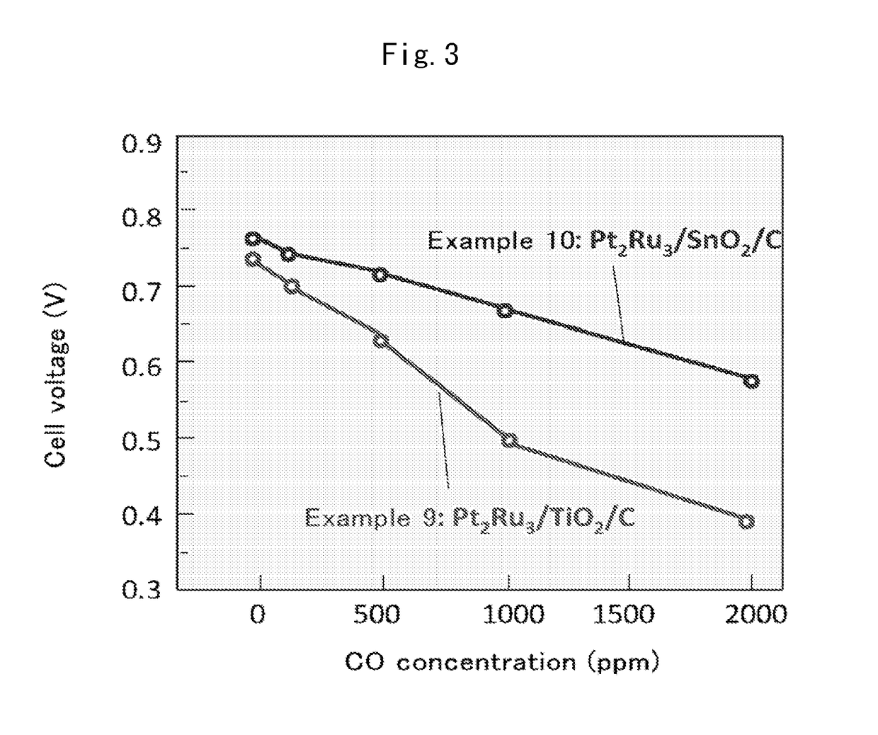
[0017]According to the present invention, a fuel cell anode catalyst with markedly enhanced CO tolerance is obtained. The present invention further provides a fuel cell anode employing the above catalyst and having markedly enhanced CO tolerance, a fuel cell membrane electrode assembly employing this anode, and a fuel cell employing this fuel cell membrane electrode assembly.

Problems solved by technology

However, the conventional PtRu / C catalysts described in the above-cited patent and nonpatent references do not yet afford adequate CO tolerance.

Method used


Image

  • Fuel cell anode catalyst and manufacturing method therefor
  • Fuel cell anode catalyst and manufacturing method therefor
  • Fuel cell anode catalyst and manufacturing method therefor

Examples


example 1

(1)-1 Method of Supporting Pt

[0068]1. A 0.56506 g quantity of TKK carbon E support (specific surface area 900 m2 / g), 8.2675 g of dinitrodiamine platinum nitrate solution, and a small quantity of distilled water were mixed ultrasonically. Distilled water was added to make a total of 200 mL of distilled water, and 25 mL of ethanol was added.

2. A reflux tube was attached and stirring was conducted at 92° C. or higher for 8 hours.

3. Washing and filtering were conducted with about 1 L of distilled water.

(1)-2 Method of Supporting Ru

[0069]1. A 0.75745 g quantity (ratio (molar ratio) of Pt and Ru:1:3) of RuCl3n(H2O) and a small quantity of distilled water were mixed ultrasonically. The mixture was charged to a three-necked flask, distilled water was added to make a total quantity of 85 mL of water, and 9 mL of methanol was added.

2. Reflux reduction was conducted while stirring at 65° C. for 6 to 8 hours. Although the color dissipated considerably, it did not disappear entirely. The tempera...

example 2

[0075]With the exceptions that the quantity of RuCl3.nH2O employed was changed from 0.75745 g to 0.378 g and the ratio (molar ratio) of Pt and Ru was adjusted to 2:3, a PtRu / C catalyst was obtained in the same manner as in Example 1.

[0076]STEM measurement of the PtRu / C catalyst particles obtained revealed the average particle diameter of the PtRu particles to be 2.35 nm and the standard deviation in the particle diameter to be 1.16 nm.

example 3

[0077]With the exception that TKK carbon E support was replaced with porous carbon (specific surface area 1,800 m2 / g), a PtRu / C catalyst was obtained in the same manner as in Example 1. STEM measurement of the PtRu / C catalyst obtained revealed the average particle diameter of the PtRu particles to be 2.35 nm and the standard deviation in the particle diameter to be 1.16 nm.


PUM

PropertyMeasurementUnit
temperatureaaaaaaaaaa

Abstract

Provided is a fuel cell anode catalyst in which a platinum-ruthenium alloy is supported on a carbon material, and a manufacturing method therefor. The molar ratio (Pt:Ru) of the alloy is in the range of 1:1-5. When the coordination numbers of the Pt atom and the Ru atom of an atom site in the alloy, as measured by x-ray absorption fine structure, are expressed as N(Pt) and N(Ru) respectively, then N(Ru) / (N(Pt)+N(Ru)) in the platinum site is in the range of 0.8-1.1 times the theoretical value, and N(Pt) / (N(Ru)+N(Pt)) in the Ru site is in the range of 0.8-1.1 times the theoretical value. The average particle diameter of the alloy is in the range of 1-5 nm, and the standard deviation for the particle diameter is in the range of 2 nm or lower. Further provided is: a fuel cell anode with an anode composition layer, on a substrate surface, which contains the catalyst and a proton conductive polymer; a fuel cell membrane electrode assembly with a polymer electrolyte membrane sandwiched between the anode and a cathode; and a fuel cell containing the fuel cell membrane electrode assembly.

Description

CROSS-REFERENCE TO RELATED PATENT APPLICATION[0001]The present application is a Divisional of application Ser. No. 14 / 007,325, filed Sep. 24, 2013, which is national phase application of PCT Application No. PCT / JP2012 / 057109, filed Mar. 21, 2012, which claims priority to Japanese Patent Application 2011-068296, filed on Mar. 25, 2011, the entire contents of which are hereby incorporated by reference.TECHNICAL FIELD[0002]The present invention relates to a catalyst for anode for fuel cell (hereinafter a fuel cell anode catalyst) and to a method for manufacturing the same. The present invention further relates to a fuel cell anode employing this catalyst, a fuel cell membrane electrode assembly employing this anode, and a fuel cell employing this fuel cell membrane electrode assembly.BACKGROUND ART[0003]Background Technology[0004]Solid polymer fuel cells can achieve higher energy efficiency than conventional power generating techniques. As a result, their practical application as a pow...

Claims


Application Information

Patent Timeline
Patent Type & Authority Applications(United States)
IPC IPC(8): H01M4/92
CPCH01M2004/8684H01M4/926B82Y30/00H01M4/881H01M4/921H01M8/1004Y02E60/50Y02P70/50H01M4/9058
Inventor TAKEGUCHI, TATSUYAASAKURA, KIYOTAKA
Owner NATIONAL UNIVERSITY
Why Eureka
Eureka Blog
Learn More