Bleeder control arrangement

a control arrangement and bleeder technology, applied in the direction of lighting devices, electrical equipment, light sources, etc., can solve the problems of undesirable visible flicker in the light output, difficult or impossible for the led lamp driver to continuously draw the required minimum holding current, and low average current draw of modern led drivers, so as to improve the performance of the bleeder activation circuit and reliably turn on the first transistor switch

Inactive Publication Date: 2017-04-06
SIGNIFY HLDG BV
View PDF0 Cites 29 Cited by
  • Summary
  • Abstract
  • Description
  • Claims
  • Application Information

AI Technical Summary

Benefits of technology

[0009]An advantage of the bleeder control arrangement according to the invention is that the bleeder is only activated if a dimmer is present and in use, i.e. if a phase-cut is being performed on the voltage input signal. The bleeder control arrangement responds to a detected phase-cut by issuing an output signal to activate the bleeder. This can then function as intended to ensure compatibility between the LED driver and the dimmer. If there is no dimmer present, i.e. there is no dimmer connected between the load and the power supply, the bleeder control arrangement according to the invention ensures that the bleeder is never activated. In this way, the bleeder is prevented from needlessly dissipating power in situations where there is no phase-cut being performed. Furthermore, the bleeder control arrangement operates independently of whether or not a dimmer is connected between the power supply and the load, greatly simplifying the design of a power-efficient product that must be made compatible with a dimmer, but which can be used with or without a dimmer.
[0011]An advantage of the LED lamp driver according to the invention is that the LED lamp driver is automatically compatible with any kind of phase-cut dimmer, but can just as well be used without a dimmer between it and a power supply. This makes it possible to manufacture a wide range of LED lamps with such LED lamp drivers for retro-fitting into existing lighting arrangements that may or may not already include a dimmer.
[0013]An advantage of the lighting arrangement according to the invention is that an efficient operation of the LED lamp driver is ensured, even if there is no dimmer in use between the power supply and the load, or even if a dimmer is present but not active, i.e. the power supply input signal is not cut.
[0024]The amplitude of the edge detector output may in some cases be insufficient to reliably turn on the first transistor switch. Therefore, in a preferred embodiment of the invention, the bleeder control arrangement comprises an amplifying circuit portion for amplifying the output signal of the edge detection circuit portion. This can improve the performance of the bleeder activation circuit for short phase-cut portions, for example if only very little dimming is being done, and the conducting angle is close to 180°.
[0026]The bleeder control arrangement according to the invention can be realized as a self-contained module for connection between an existing dimmer and an existing electronic driver of a lamp. Such a module can then be used to retro-fit existing units and to improve the efficiency of an existing electronic driver while still ensuring compatibility between the driver and the dimmer. However, in a preferred embodiment of the invention, the bleeder control arrangement is incorporated in the driver circuit of a lamp. This simplifies the overall design, since the output of the bleeder control arrangement can be directly connected to the bleeder circuitry. The output signal from the bleeder control arrangement, indicating that the bleeder should be deactivated or activated as appropriate, can interface to an existing bleeder by means of appropriate circuit components. An exemplary arrangement will be described below.

Problems solved by technology

A modern LED driver draws a relatively low average current, which is a problem when the LED driver is to be used in conjunction with a dimmer.
As a result, it may be difficult or impossible for the driver of an LED lamp to continuously draw the required minimum holding current.
This often leads to misfiring of the phase-cut dimmer, and this in turn can result in undesirable visible flicker in the light output by the LED lamp.
However, such a bleeder dissipates a significant amount of power, for example in the range of 1.0-2.0 Watt during operation even if there is no dimmer present, or the dimmer is not performing any phase-cut.
However, the need to incorporate such digital or mixed-signal circuitry in a lamp driver adds considerably to its expense.

Method used


Image

  • Bleeder control arrangement
  • Bleeder control arrangement
  • Bleeder control arrangement

Examples


first embodiment

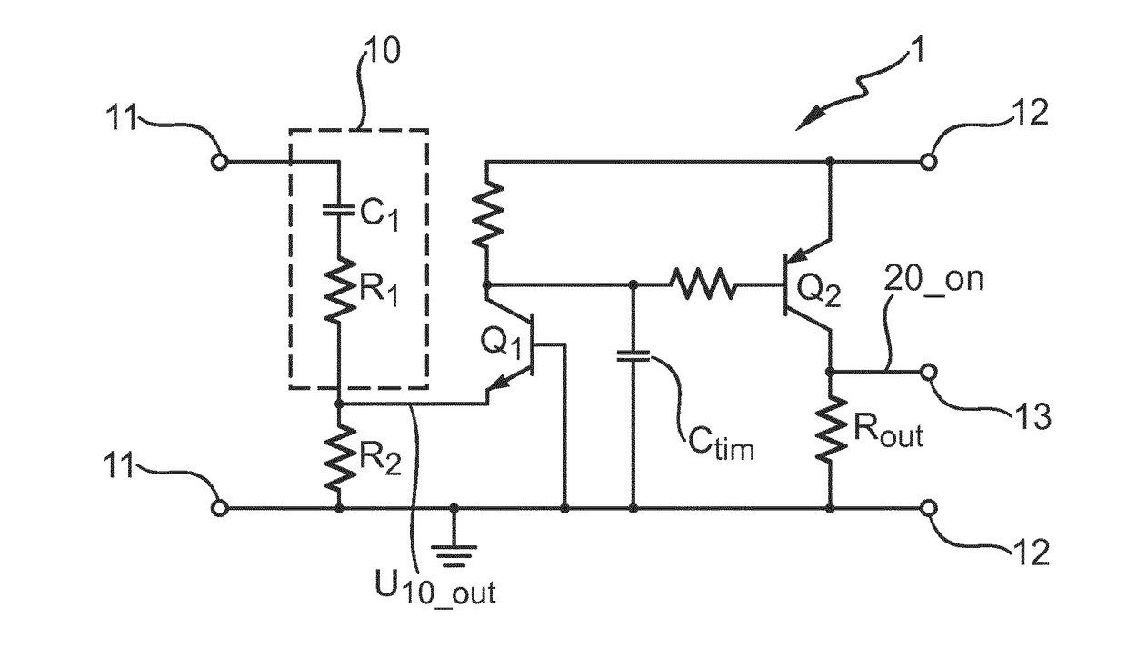
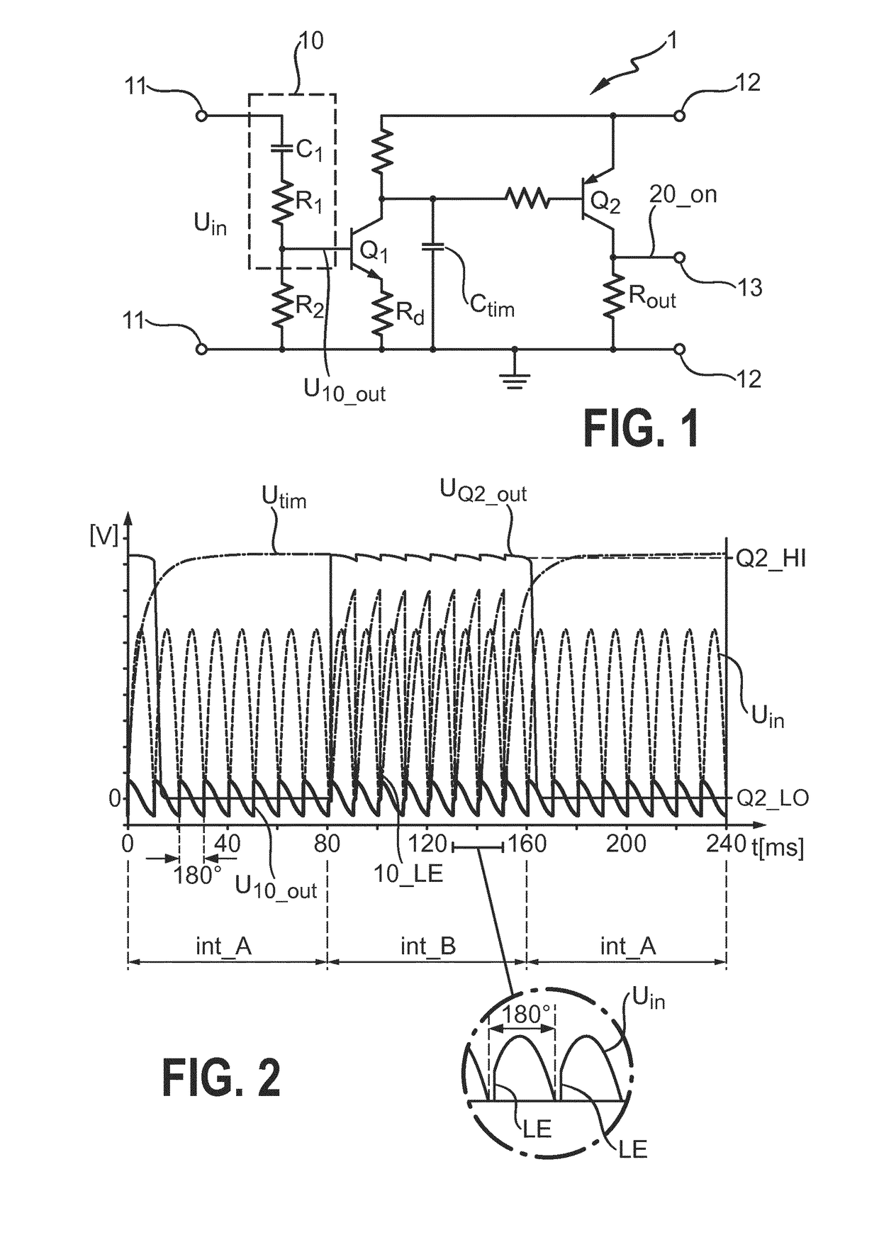
[0040]FIG. 1 shows a simplified circuit diagram of a bleeder control arrangement 1 according to the invention, comprising an edge detector 10, a first transistor switch Q1, a timing capacitor Ctim, and a second transistor switch Q2. The bleeder control arrangement 1 is used to activate a bleeder of a lamp driver if a dimmer, connected between driver and power supply, is actively cutting portions of the power input signal. The input voltage Uin to the bleeder control arrangement 1 will therefore be a rectified voltage signal that may or may not have been subject to phase cutting. The input voltage Uin is applied across input terminals 11. An auxiliary voltage supply, from which a bleeder activation signal 20_on will be derived, is not shown here but will be understood to be connected across terminals 12. The first transistor switch Q1 is an NPN BJT, while the second transistor switch Q2 is a PNP BJT. A sharply increasing rising edge of a leading-edge phase-cut signal is detected by t...

second embodiment

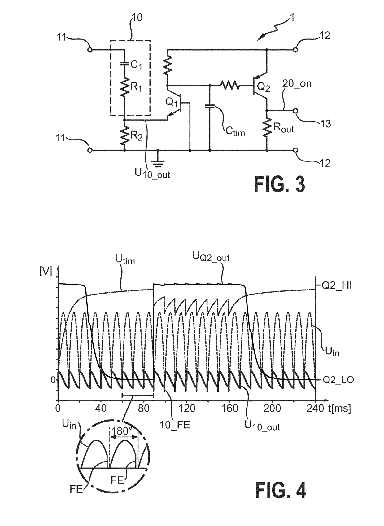
[0042]FIG. 3 shows a simplified circuit diagram of a bleeder control arrangement 1 according to the invention. This embodiment is used to detect and respond to a trailing-edge phase cut on the input voltage signal. The circuit is largely identical to that of FIG. 1, but the output of the edge detector 10 is connected instead to the emitter of the first transistor switch Q1, which in this case is also an NPN BJT. A falling edge of a trailing-edge phase-cut signal is detected by the edge detector 10, which responds by generating a brief negative pulse, which again acts to open a discharge path for the timing capacitor Ctim through the first transistor switch Q1 and resistor R2. Again, the output of the bleeder control arrangement 1 is measured across a resistor Rout between the collector of the PNP transistor Q2 and ground.

[0043]FIG. 4 shows graphs of relevant signals of the bleeder control arrangement of FIG. 3. The input voltage Uin is again subject to phase-cutting during a phase-c...

third embodiment

[0046]FIG. 7 shows a simplified circuit diagram of a bleeder control arrangement 1 according to the invention. Here, the bleeder control arrangement 1 can detect and respond to both a leading-edge and a trailing-edge on a phase-cut signal. In other words, this embodiment of the bleeder control arrangement 1 can be used to detect the action of a leading-edge phase-cut dimmer and / or the action of a trailing-edge phase-cut dimmer. This embodiment is basically the embodiment of FIG. 1, extended to include the functionality of the embodiment of FIG. 3. Leading-edge detection is dealt with by a leading-edge transistor switch Q1LE. Trailing-edge detection is dealt with by another transistor switch Q1FE. This embodiment also shows a ‘logic inverter’14 which can be connected to the collector of the second transistor switch Q2 in order to obtain an output signal with inverted polarity, if such inversion is required. This additional circuitry can be provided so that the bleeder control arrange...


PUM


Abstract

The invention describes an analogue bleeder control arrangement (1) realized for use between a power supply (4) and a load (3), which bleeder control arrangement (1) is realized to generate a bleeder activation signal (20_on) to activate a bleeder (20) arranged between the power supply (4) and the load (3), and wherein the bleeder activation signal (20_on) is generated only upon detection of a phase-cut edge (LE, FE) on a voltage input signal (Uin). The invention further describes an LED lamp driver (2), realized to drive a lighting load (3) comprising a number of LED light sources (30) and comprising such a bleeder control arrangement (1). The invention also describes a lighting arrangement (6) comprising an LED lighting load (3); a driver circuit (2) realized to drive the lighting load (3); a bleeder (20) for providing compatibility between a dimmer (5) and the driver (2); and such a bleeder control arrangement (1) realized to activate the bleeder (20) only upon detection of a phase-cut edge (LE, FE) on a power supply input signal (Uin).

Description

FIELD OF THE INVENTION[0001]The invention describes a bleeder control arrangement; an LED lamp driver; and a lighting arrangement.BACKGROUND OF THE INVENTION[0002]The use of LED-based lamps is becoming more widespread in home and office environments, since LEDs are efficient and can be realized in a wide range of designs and to deliver precise color temperatures. If an LED-lamp is to be connected to an already installed dimmer, it must be compatible to it. Dimmers of the type used between a power supply and a light source are generally leading-edge or trailing-edge phase-cut dimmers. These work by “cutting off” or suppressing a portion of a sinusoidal mains signal in order to reduce the input power to the light source, either at the beginning of a sinusoidal half-wave (leading edge) or at the end of a sinusoidal half-wave (trailing edge) of a full-wave rectified voltage signal. By ‘removing’ a portion of the input voltage to the lamp, less energy is passed to the following driver el...

Claims


Application Information

Patent Timeline
Patent Type & Authority Applications(United States)
IPC IPC(8): H05B33/08H05B44/00
CPCH05B33/0845H05B33/0887H05B45/395H05B45/00H05B45/31H05B45/315H05B45/10H05B45/375H05B45/3575
Inventor HILGERS, ACHIMMALYNA, DMYTRO VIKTOROVYCH
Owner SIGNIFY HLDG BV
Why Eureka
Try Eureka