Process to Design and Install Wind Towers by Utilizing Some of the Existing Drilling Technologies

a technology of wind turbines and drilling technologies, applied in the direction of machines/engines, mechanical equipment, greenhouse gas reduction, etc., can solve the problems of unoptimized efficiency of wind turbines, and achieve the effect of efficiently harnessing the kinetic energy of wind turbines and converting them into electricity

Active Publication Date: 2017-04-13
OZCAN HUSEYIN
View PDF0 Cites 3 Cited by
  • Summary
  • Abstract
  • Description
  • Claims
  • Application Information

AI Technical Summary

Benefits of technology

[0005]As wind blows past a turbine, the blades capture the energy and rotate. This rotation triggers an internal shaft to spin, which is connected to a gearbox increasing the speed of rotation, which connects to a generator that ultimately produces electricity. Most commonly, wind turbines consist of a steel tubular tower, of at least 100 feet, which supports both a “hub” securing wind turbine blades and the “nacelle” which houses the turbine's shaft, gearbox, generator and controls. A wind turbine is equipped with wind assessment equipment and will automatically rotate into the face of the wind, and angle or “pitch” its blades to optimize energy capture.
[0014]The pole is constructed with smaller tapered threaded casing joints which are assembled joint by joint with its lower end disposed below ground level within a wellbore The pole includes wind breakers at certain intervals to reduce bending stress due to wind forces. The casing within the welbore serves as a cylinder wherein the pole acts like a piston therein. The cylinder contains a lighter liquid causing the pole to submerge therein. By adding heavier liquid within casing the pole is raised above ground through hydraulic pressure.

Problems solved by technology

Although HAWTs have achieved widespread usage, their efficiency is not optimized.

Method used


Image

  • Process to Design and Install Wind Towers by Utilizing Some of the Existing Drilling Technologies
  • Process to Design and Install Wind Towers by Utilizing Some of the Existing Drilling Technologies
  • Process to Design and Install Wind Towers by Utilizing Some of the Existing Drilling Technologies

Examples


Embodiment Construction

[0035]A more complete understanding of the processes and apparatuses disclosed herein can be obtained by reference to the accompanying drawings. These figures are merely schematic representations based on convenience and the ease of demonstrating the existing art and / or the present development, and are, therefore, not intended to indicate relative size and dimensions of the assemblies or components thereof.

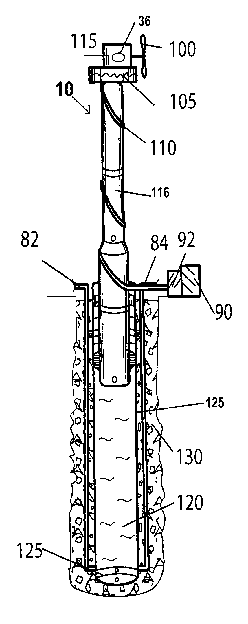
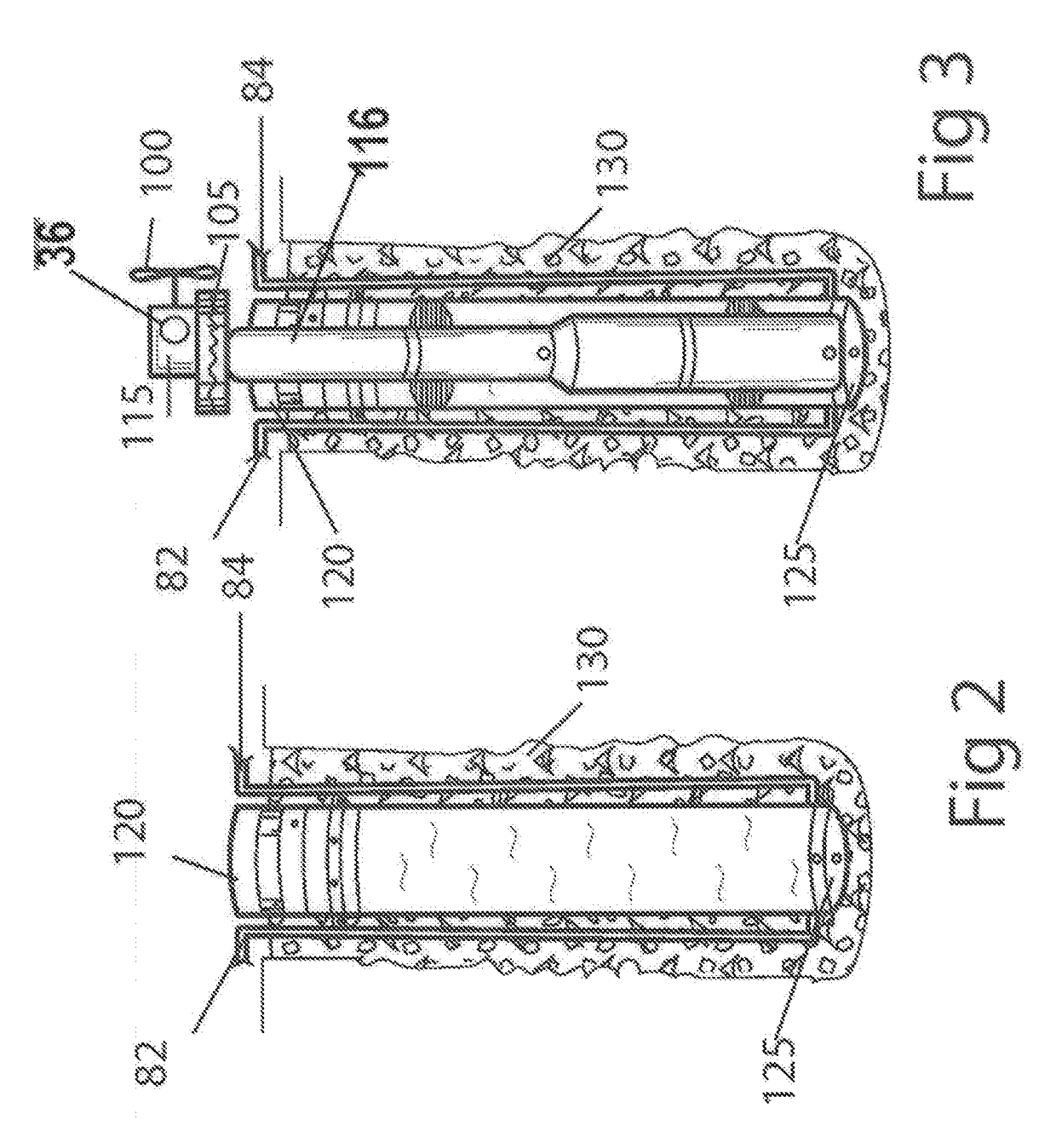
[0036]As depicted in FIG. 3, the improved wind turbine system (10) of the present invention comprises a wind assembly (115) that drives a power generator assembly installed at ground level. As shown in FIG. 5, the wind turbine assembly comprises a pumping unit (36) operationally coupled to an impeller (100). As depicted the wind turbine assembly is supported by a tank (105) disposed atop a tower situated at an elevation level of at least 100 feet above ground level. In the present invention, the wind stream is collected by the wind turbine assembly (115) which is operationally cou...


PUM


Abstract

The present invention is an improved arrangement for a wind turbine system wherein the power generator unit is independently installed at ground level to minimize the vertical compressive load imposed on the poles. The wind turbine system is powered by an integrated hydraulic power unit comprising a hydraulic pump driving a hydraulic motor operationally coupled to the power generator at ground level. A lighter weight hydraulic pump replacing the old system generator is operationally coupled to the wind turbine rotor blades disposed atop the pole. An umbilical hose supplies high pressurized fluid from the hydraulic pump to the hydraulic motor thereby causing the power generator to rotate.

Description

BACKGROUND OF THE INVENTION[0001]This application claims the benefit of Provisional Application 62 / 122,527[0002]This invention relates to wind turbines more particularly an improved method of harnessing wind power thereby converting kinetic energy to generate electrical energy.[0003]Windmills have been known and used for centuries as power generators and typically have been used to pump water and to grind grains such as wheat and corn. Because energy from the wind is free and non-polluting, much attention has been given to improving the efficiency and lowering the cost of windmill structures. Wind power has increased exponentially since the dawn of the 21st century. The amount of power that a conventional or propeller type windmill can generate is directly proportional to the square of the diameter of the circle of rotation of the blade tips and also to the cube of the wind velocity.[0004]A wind turbine converts kinetic energy from the wind into electrical power. Generally, wind tur...

Claims


Application Information

Patent Timeline
Patent Type & Authority Applications(United States)
IPC IPC(8): F03D80/80F03D1/06E04H12/08F03D9/00E04H12/18F03D13/20F03D7/02
CPCF03D80/80F03D13/20F03D1/0675E04H12/08F03D9/002E04H12/182F03D7/0236Y02E10/728F05B2240/9151Y02E10/72Y02P80/10Y02E70/30F03D9/11
Inventor OZCAN, HUSEYIN
Owner OZCAN HUSEYIN
Why Eureka
Try Eureka