Asymmetric floats for wave energy conversion

a wave energy conversion and asymmetric technology, applied in the direction of mechanical equipment, machines/engines, electric generator control, etc., can solve the problems of not being the most efficient structure, known axis-symmetric structures, etc., to improve the power generation efficiency and survivability of wecs, improve the efficiency of wecs, and achieve optimal performance. , the effect of high energy captur

Inactive Publication Date: 2014-09-18
BRETL JAMES G +1
View PDF8 Cites 4 Cited by
  • Summary
  • Abstract
  • Description
  • Claims
  • Application Information

AI Technical Summary

Benefits of technology

[0010]Asymmetric floats-Applicants' invention is directed to asymmetrical float shapes which have been designed to have a geometry which will optimize energy capture from ocean waves for various sea states. This is based, in part, on the recognition that the directional performance of the shape is of interest. A study of the power performance as a function of the shape of the float relative to incident wave direction showed an improvement in the power generation efficiency and survivability of the WECs. This...

Problems solved by technology

However, known axis-symmetric structures are not the most efficient structures when it comes to optimizing wave energy capture and power gen...

Method used


Image

  • Asymmetric floats for wave energy conversion
  • Asymmetric floats for wave energy conversion
  • Asymmetric floats for wave energy conversion

Examples


Embodiment Construction

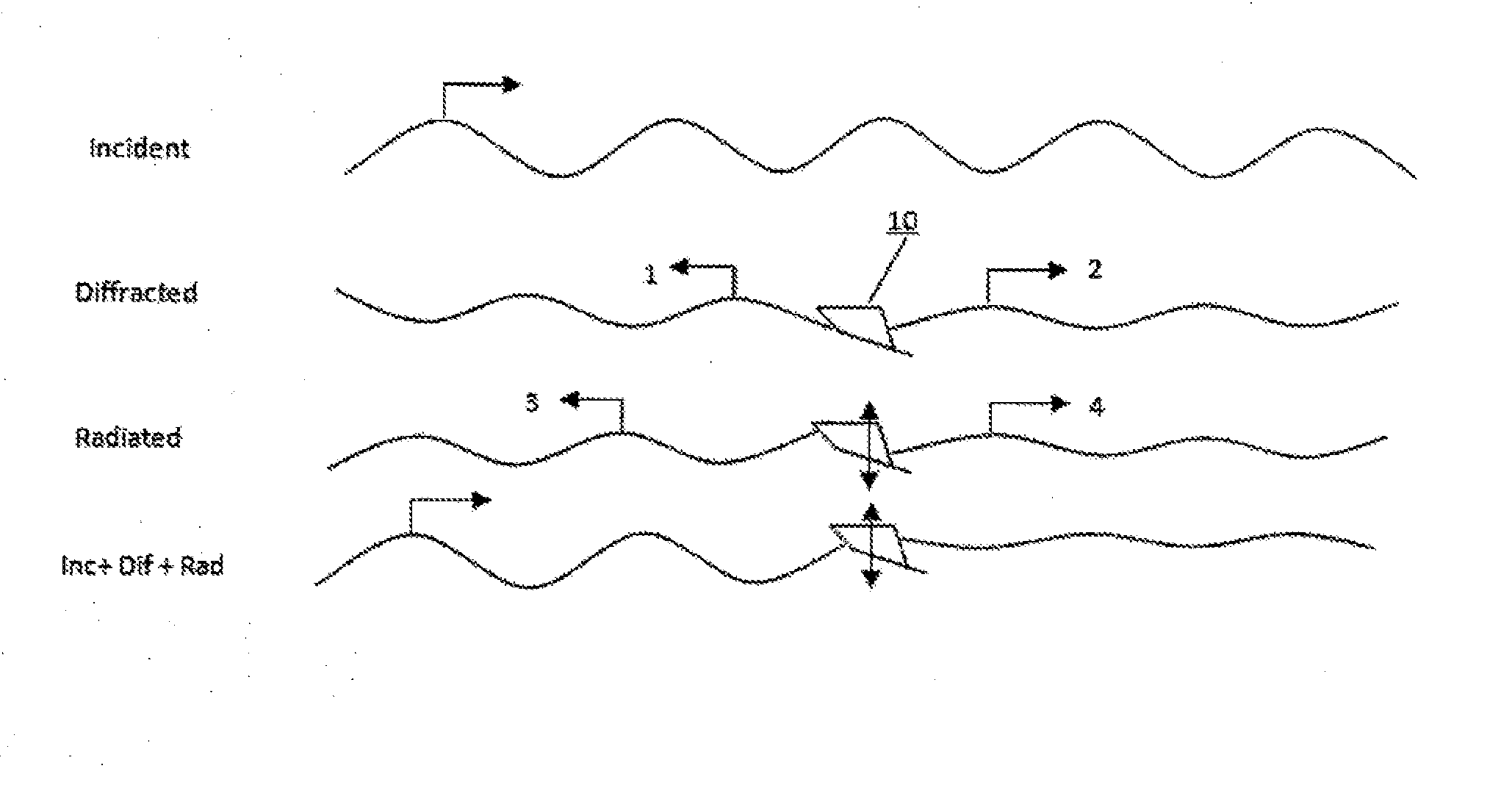
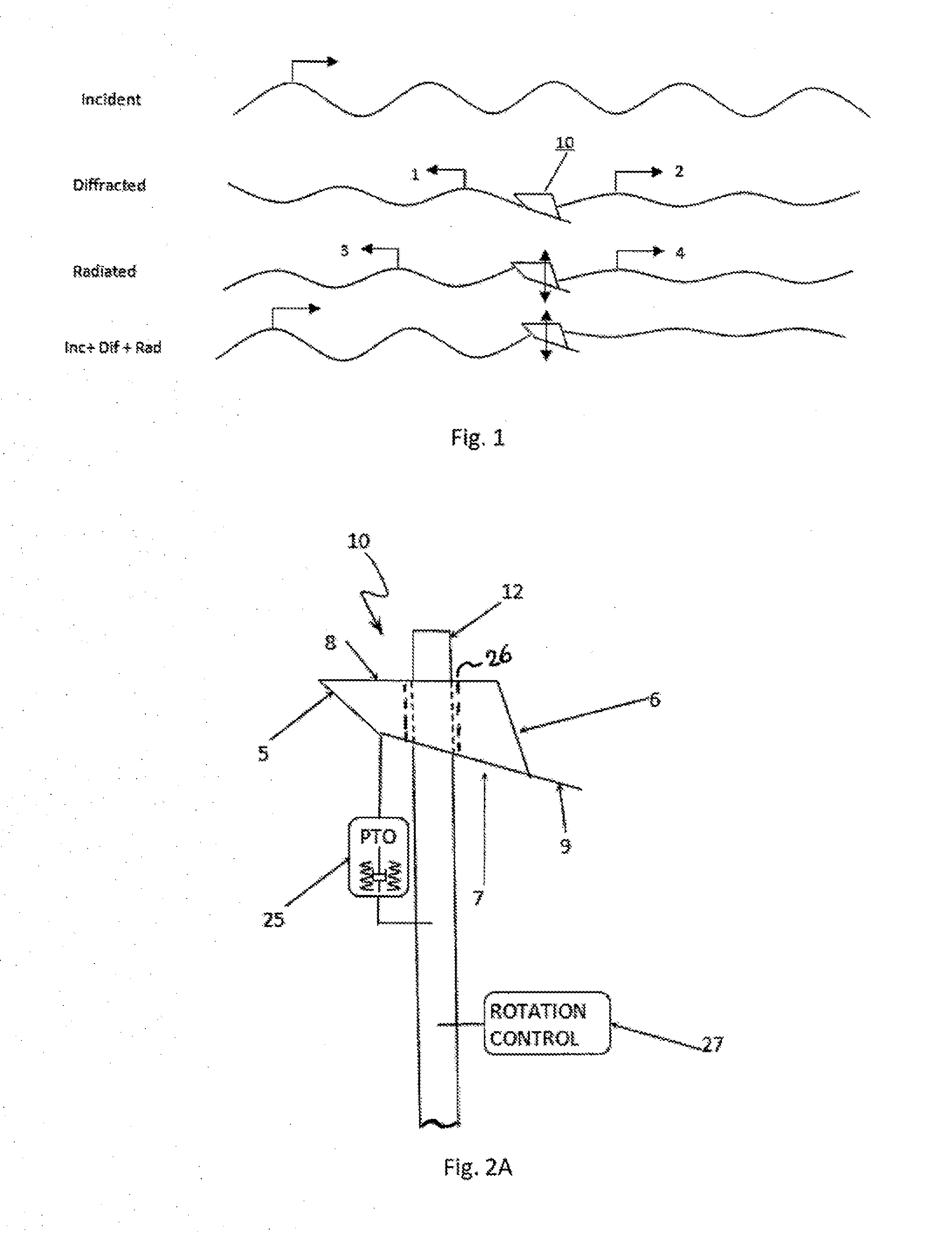
[0027]FIG. 1 is a two-dimensional representation of a floating body 10 embodying the invention which may be used to form a wave energy converter (WEC). FIG. 1 shows the floating body 10 in the presence of an incident wave (travelling from left to right in FIG. 1) and illustrates that a good wave absorber must be a good wave maker. The waves caused by the body 10 are broken down into the two components, diffracted and radiated. The diffracted wave is a result of the incident wave and the presence of the body in the absence of any motion. The radiated wave is the result of the motion of the body in otherwise calm water.

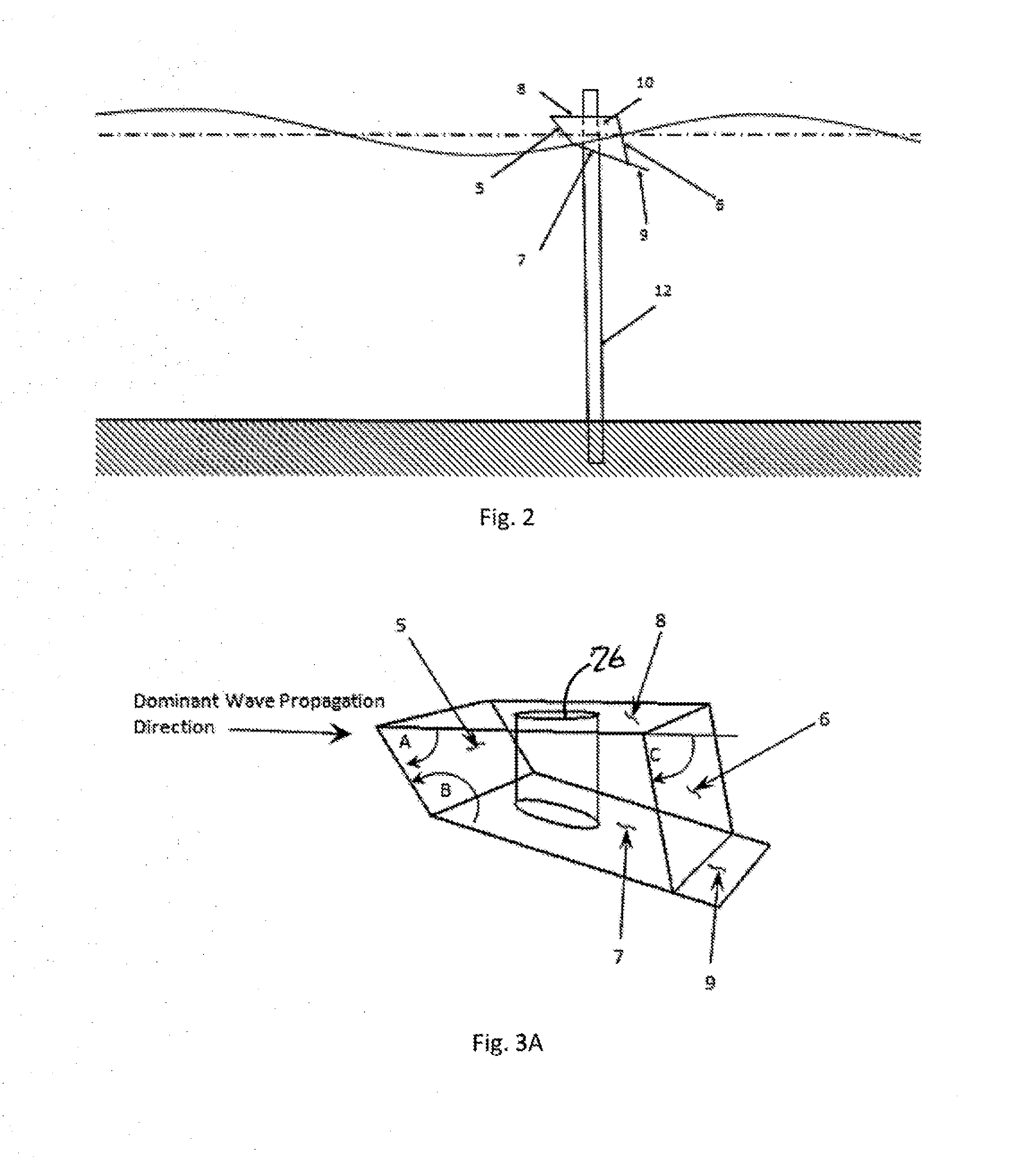
[0028]Consider the floating body 10 to have a prismatic (depth) float shape that is extruded in a direction parallel to the wave crest. In the limiting case of a long prism, this becomes a 2-dimensional or long crested wave problem. As such, the disturbance waves can each be further broken down into two components. One set of disturbances propagates in the same directio...


PUM


Abstract

A wave energy converter (WEC) includes a prismatic float having a quadrilateral-like cross section including a front plate, for facing incoming waves, a top plate, a bottom plate and a back plate. The front plate is connected at its top edge to the front end of the top plate which is disposed to be generally parallel to the surface of the water and at its bottom edge to the front end of the bottom plate. The plates are interconnected such that the sides of the top and front plates define an acute angle and the sides of the front and bottom plates define an obtuse angle. The back panel is connected between the back end of the top plate and the back end of the bottom plate. The exterior angle between the back panel and the top plate is generally less than 90 degrees. An extension plate may be added to the bottom plate which extends rearward of the float.

Description

[0001]This application claims priority based on an application Ser. No. 61 / 685,125 filed Mar. 12, 2012 whose teaching and subject matter are incorporated herein by reference.BACKGROUND OF THE INVENTION[0002]This invention relates to wave energy converters (WECs) for converting energy present in water waves into useful energy and, in particular, to floats, and their design, for use in wave energy converters (WECs) to provide improved power conversion efficiency. That is, this invention relates to apparatus for converting energy present in surface of bodies of water into useful energy and, in particular, to the design of floats (or shells) for use in wave energy converters.[0003]Known WEC systems generally include a “float” (or “shell”) and a “spar” (or “shaft” or “column” or “piston”) which are designed to move relative to each other to convert the force of the waves into mechanical energy. In these systems, the float is generally depicted or referred to as the moving member and the ...

Claims


Application Information

Patent Timeline
IPC IPC(8): F03B13/12
CPCF03B13/12F03B13/1845F05B2240/40F05B2250/20F05B2250/73Y02E10/30
Inventor BRETL, JAMES G.EDER, JAMES
Owner BRETL JAMES G
Why Eureka
Try Eureka