Bearing cage with antenna and method for detecting failure of a bearing cage

a technology of bearing cage and antenna, which is applied in the direction of mechanical equipment, rotary machine parts, transportation and packaging, etc., can solve the problems of difficult integration of batteries or generators into bearing cages, narrow available space, and rotating bearing cages, etc., to achieve easy and reliably detection, increase the surface area, and increase the likelihood

Active Publication Date: 2017-04-13
AB SKF
View PDF2 Cites 6 Cited by
  • Summary
  • Abstract
  • Description
  • Claims
  • Application Information

AI Technical Summary

Benefits of technology

[0013]In one embodiment, the antenna coil is executed as a single loop that extends around the full circumference of the cage main body. Is some examples, the single loop is provided on an axially oriented side face of the cage. In other examples, the single loop is provided on a radially oriented surface of the cage. The single loop may then include sections that extend in an axial direction of the cage, between adjacent pockets of the cage, and further include sections that extend in a circumferential direction of the cage, between an axial side of the cage pockets and a lateral rim of the cage. Such an execution increases the surface area of the cage main body that is covered by the inductor coil, thereby increasing the likelihood that even a small local crack in the cage will cause a rupture in the antenna coil.
[0014]The advantage of a single loop is that a rupture of the antenna coil at any location results in the passive resonant circuit losing its ability to resonate. This can be easily and reliably detected in order to determine that cage failure has occurred.

Problems solved by technology

However, a bearing cage is rotating and cannot be easily accessed and the available space is narrow.
In particular for smaller bearings, it is difficult to integrate batteries or a generator into the bearing cage.
However, this solution is feasible only for larger bearings with a cage capable of supporting the transmitter electronics.
While the polyamide cages have turned out to be safer than the formerly used steel cages, the defects in polyamide cages will not be detectable using the hot-box infrared scanners.

Method used


Image

  • Bearing cage with antenna and method for detecting failure of a bearing cage
  • Bearing cage with antenna and method for detecting failure of a bearing cage
  • Bearing cage with antenna and method for detecting failure of a bearing cage

Examples


Embodiment Construction

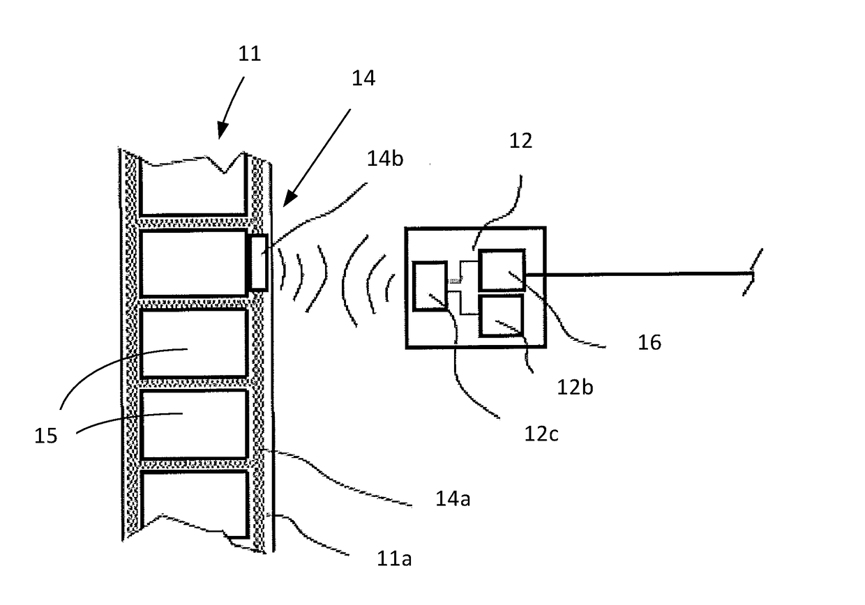
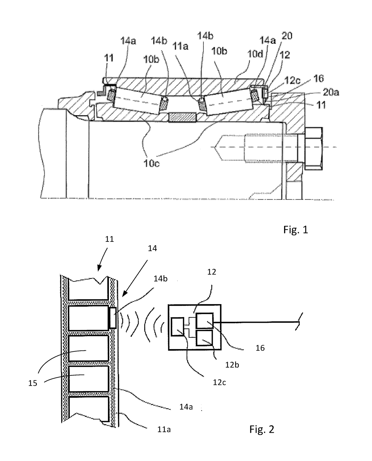
[0036]FIG. 1 illustrates a train bearing unit including a double-row tapered roller bearing 10 including two ring-shaped bearing cages 11, a split inner ring 10c and an outer ring 10d configured to accommodate two rows of rolling elements 10b of the bearing, formed as tapered rollers.

[0037]The bearing unit is equipped with a sensor assembly, which includes a transmitter 12 attached to a bearing seal 20 and configured to generate oscillating current signals in a primary coil 12c of the transmitter.

[0038]Further, the sensor assembly includes a passive resonant circuit 14 (refer FIG. 2) including an antenna coil 14a attached to the bearing cage 11, and an RFID chip 14b. The RFID chip 14b may include various sensors such as a temperature sensor.

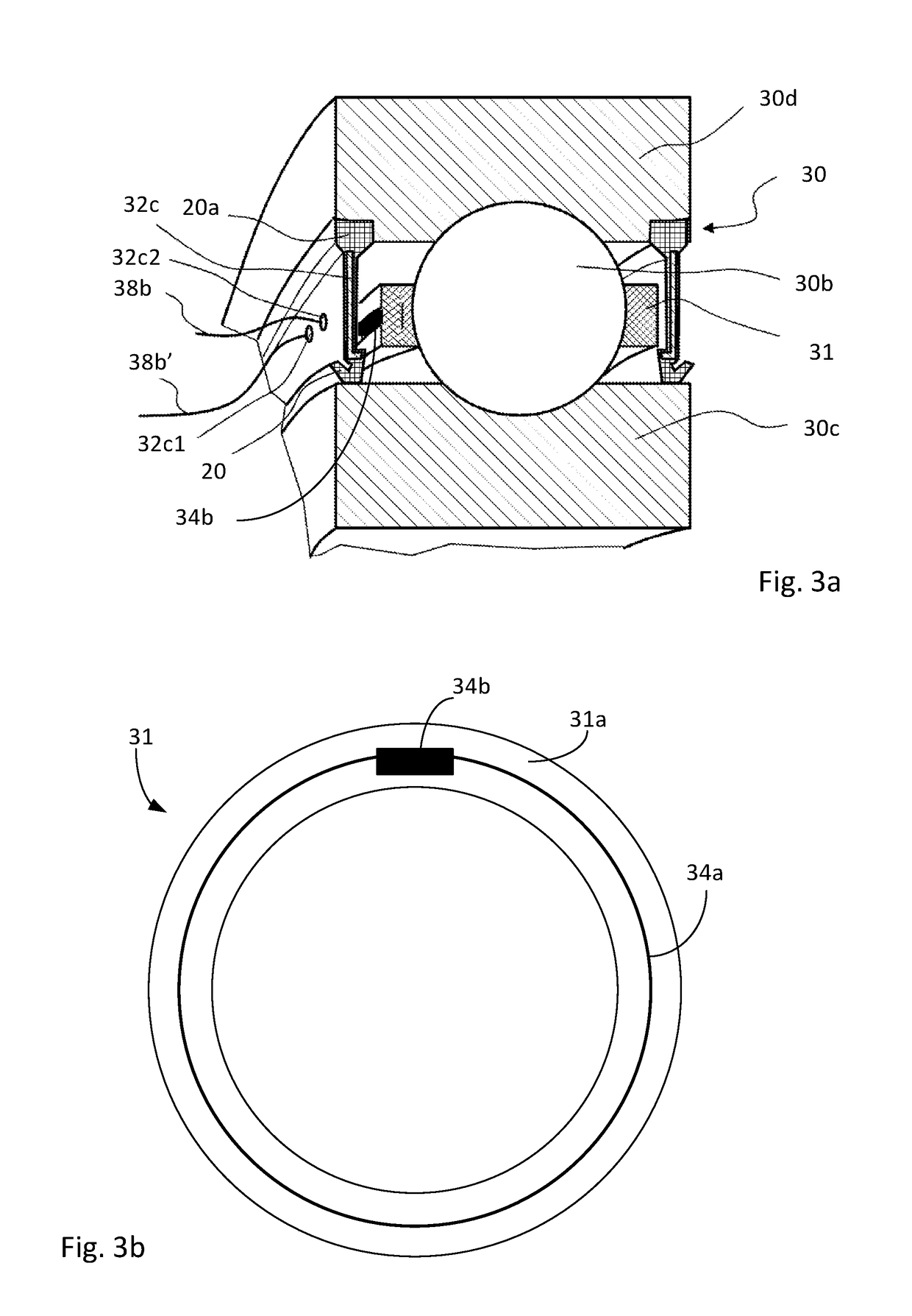
[0039]In the depicted example, the primary coil 12c is embedded in an elastomeric material 20a of the seal 20. The primary coil may also be attached to the bearing outer ring 10d and may be formed as a loop extending over the entire circumference...


PUM


Abstract

The invention relates to a bearing cage including a bearing cage main body made of a polymer material and having pockets for receiving at least one row of rolling elements of a bearing. The cage is provided with a passive resonant circuit including an antenna coil attached to the cage main body. It is proposed that the antenna coil is formed as a conductive layer directly attached to the cage material of the bearing cage main body and is designed so as to have a breaking point less than or equal to a breaking point of the cage material. Thus, a rupture in the cage main body ruptures the antenna coil, changing the resonance behaviour of the passive resonant circuit.

Description

CROSS REFERENCE TO RELATED APPLICATIONS[0001]This application claims priority to European patent application no. 15380043.8 filed on Sep. 30, 2015, the contents of which are fully incorporated herein by reference.FIELD OF THE INVENTION[0002]The invention relates to a bearing cage including an antenna. In particular, the invention relates to a bearing cage including an antenna having a passive resonant circuit including an antenna coil attached to the cage main body,BACKGROUND OF THE INVENTION[0003]It is known to provide bearings such as ball bearings or roller bearings with temperature sensors. For monitoring the bearing, heat generated at the interface of balls / rollers and the raceways is detected by a temperature sensor located as close as possible to this interface. This makes a cage of a bearing a desirable position for temperature measurement. However, a bearing cage is rotating and cannot be easily accessed and the available space is narrow. In particular for smaller bearings,...

Claims


Application Information

Patent Timeline
Patent Type & Authority Applications(United States)
IPC IPC(8): F16C41/00F16C33/46H01Q7/00F16C33/56G01M13/04F16C33/38F16C33/44
CPCF16C41/008F16C33/3831F16C33/4611F16C2233/00F16C33/56G01M13/04H01Q7/00F16C33/44F16C41/007G01R29/10F16C19/386F16C19/52F16C33/4635F16C2202/06F16C2202/40F16C2300/02F16C2326/10F16C41/002H01Q1/27
Inventor HEBRARD, YOANNLANG, DEFENGKARLSSON, ANDREASMARTINEZ, VICTORDE WIT, FRANK
Owner AB SKF
Why Eureka
Try Eureka