
Fingerprint recognition device, display screen and display device

Active Publication Date: 2017-04-13
BOE TECH GRP CO LTD +1
View PDF9 Cites 12 Cited by
  • Summary
  • Abstract
  • Description
  • Claims
  • Application Information

AI Technical Summary

Benefits of technology

The present invention provides a fingerprint recognition device with a simple structure and low cost. It includes a glass base and detecting electrodes formed on the glass base, which significantly reduces the cost compared to conventional devices having detecting electrodes formed on the silicon base. Additionally, the fingerprint recognition device does not require sapphire, which further reduces the cost and simplifies the manufacturing process. This results in improved production capacity.

Problems solved by technology

The inventors have found that at least the following problems exist in the prior art: in order to install the fingerprint recognition device 1, the protection glass 3 needs to be drilled, which makes the process complicated; the sapphire 12 needs to be used as a touch receiving device, which results in a high cost, and in addition, the detecting electrodes 111 are formed on the silicon base 11 which also has a high cost, thereby resulting in a high total cost of the fingerprint recognition device,

Method used


Image

  • Fingerprint recognition device, display screen and display device
  • Fingerprint recognition device, display screen and display device
  • Fingerprint recognition device, display screen and display device

Examples


first embodiment

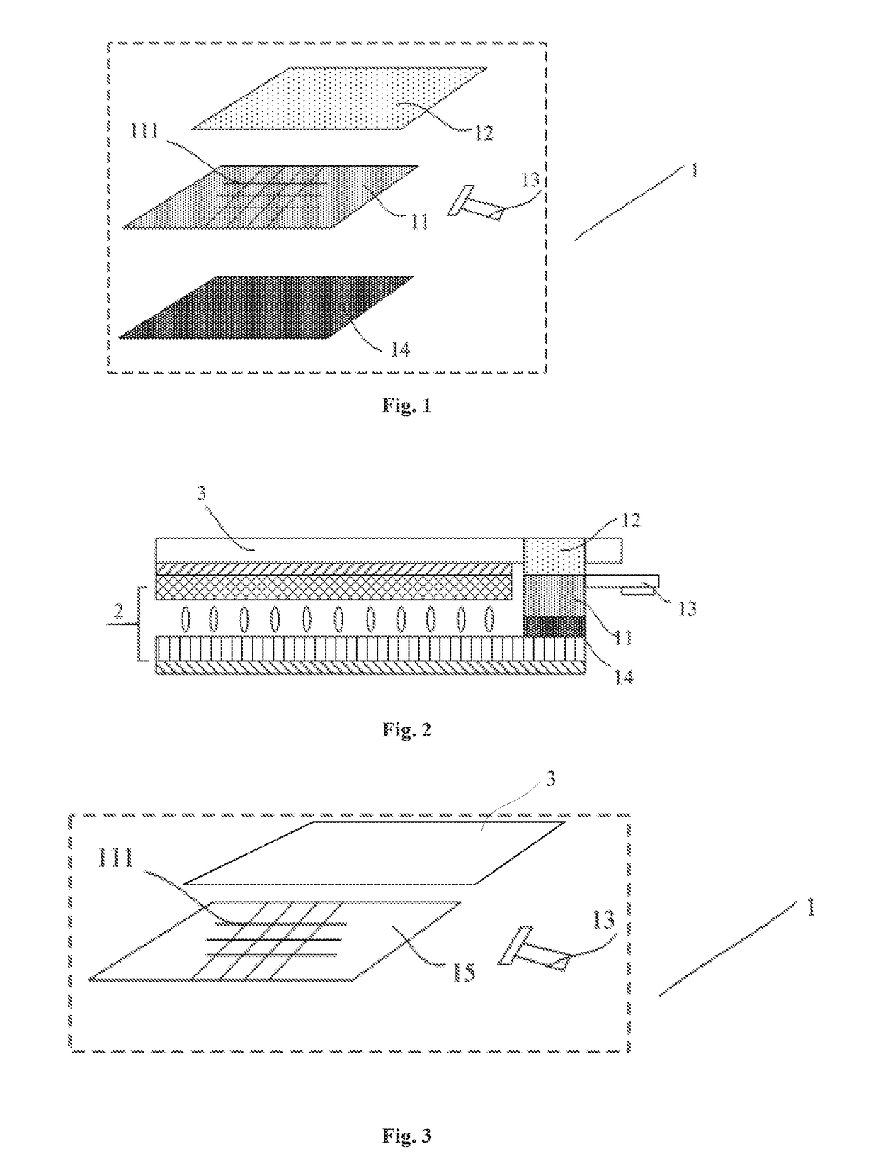
[0028]FIG. 3 is a schematic diagram of a fingerprint recognition device according to the present embodiment. As illustrated in FIG. 3, the fingerprint recognition device 1 includes a protection glass 3, a glass base 15, a plurality of detecting electrodes 111 formed on the glass base 15, and a control unit (not shown). When a finger of human touches on the protection glass 3, capacitance is formed between the plurality of detecting electrodes 111 and ridges or valleys of the fingerprint, and the fingerprint is recognized by the control unit based on the capacitance.

[0029]Since the fingerprint recognition device 1 according to the present embodiment includes a glass base 15, and the detecting electrodes 111 are formed on the glass base 15, the cost of the fingerprint recognition device 1 according to the present embodiment is significantly decreased, compared with conventional fingerprint recognition devices having detecting electrodes formed on the silicon base. In addition, the fin...

second embodiment

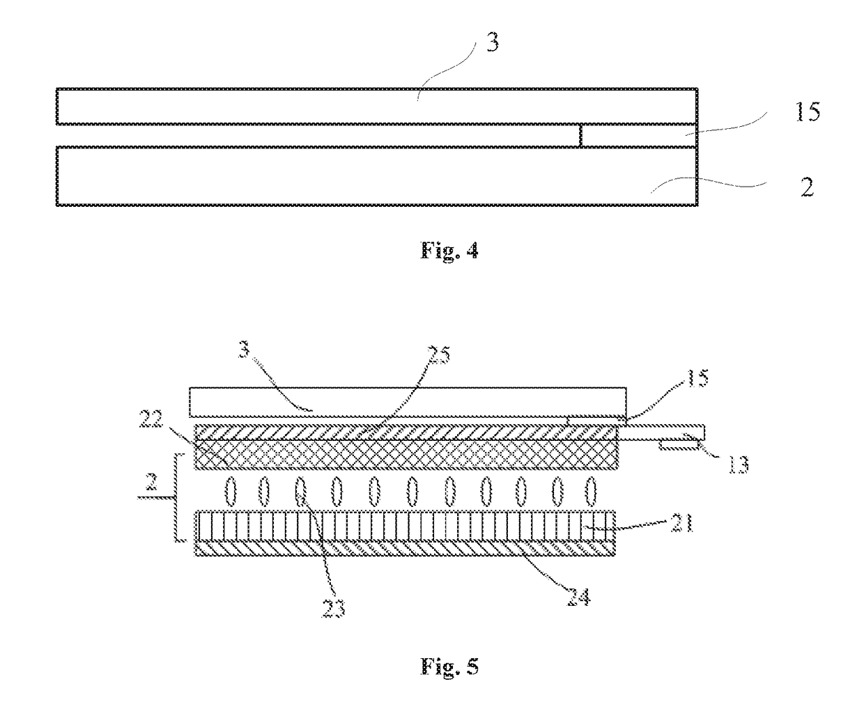
[0034]The present embodiment provides a display screen, which includes a protection glass and a display panel positioned under the protection substrate, and the display screen further includes the fingerprint recognition device 1 according to the first embodiment, wherein the fingerprint recognition device 1 and the protection glass as well as the display panel are formed integrally, thereby simplifying the manufacture procedure of the display screen according to the present embodiment.

[0035]Specifically, FIG. 4 illustrates a schematic diagram of a display screen according to the present embodiment. As shown in FIG. 4, the display screen in the present embodiment includes a protection glass 3 and a display panel 12 positioned under the protection substrate, and the display screen further includes a glass base 15 and a control unit (not shown), the glass base 15 is positioned under the protection substrate 3 and above the display panel 2, a plurality of detecting electrodes 111 are f...

third embodiment

[0043]The present embodiment provides a display device. FIG. 5 illustrates a schematic diagram of a display device according to the present embodiment, and the display device includes the above display screen, a backlight component (not shown) and the like.

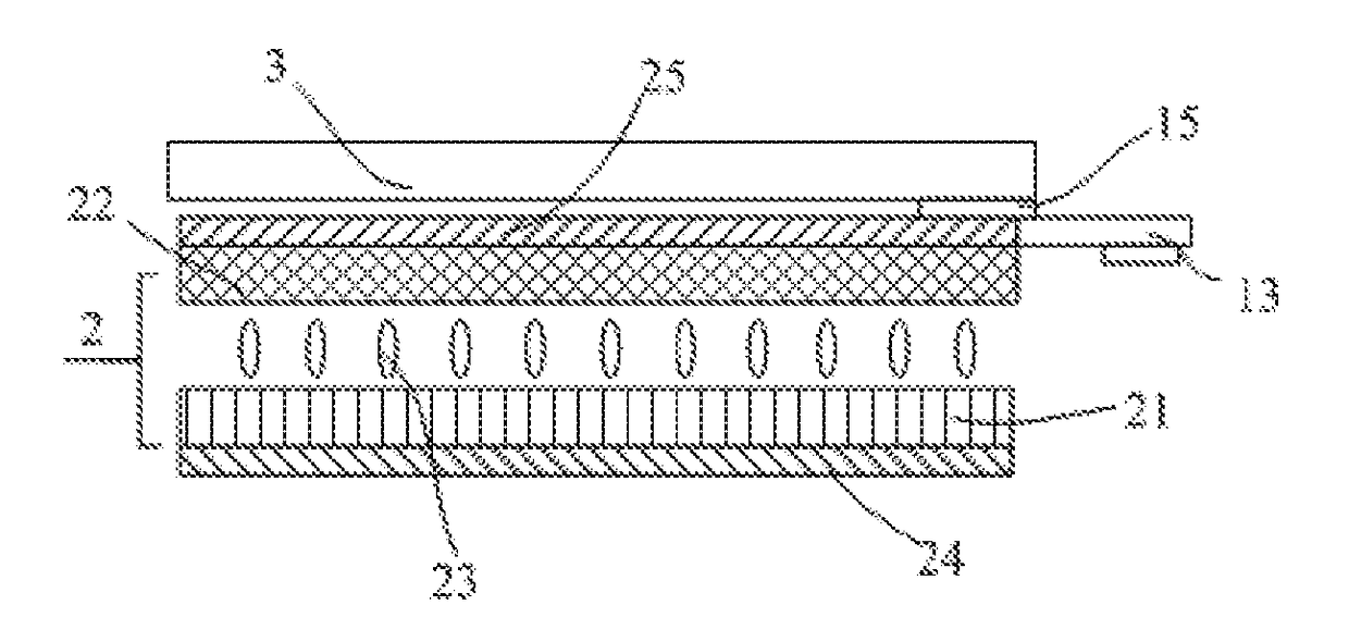
[0044]As illustrated in FIG. 5, the display screen in the second embodiment includes the fingerprint recognition device 1, which is arranged at the light emitting side of the display panel 2, wherein the display panel 2 may include an array substrate 21 and a color filter substrate 22 assembled and opposite to each other and liquid crystal molecules 23 formed between the array substrate 21 and the color filter substrate 22,

[0045]A lower polarizer 24 and an upper polarizer 25 are arranged at the light incident side of the array substrate 21 and the light emitting side of the color filter substrate 22, respectively, while the fingerprint recognition device 1 is arranged at the light emitting side of the upper polarizer 25, and there...


PUM


Abstract

The present invention provides a fingerprint recognition device, a display screen and a display device, which belong to the field of display technology and can solve the problem of high cost for conventional fingerprint recognition devices The fingerprint recognition device of the present invention arranged at a light emitting side of a display panel includes a protection substrate, a glass base positioned under the protection substrate, a plurality of detecting electrodes formed on the glass base, capacitance being formed between the plurality of detecting electrodes and ridges or valleys of a fingerprint when touching occurs, and a control unit used to recognize the fingerprint based on the capacitance. The fingerprint recognition device of the present invention has a simple structure and a low cost.

Description

FIELD OF THE INVENTION[0001]The present invention belongs to the field of display technology, and specifically relates to a fingerprint recognition device, a display screen and a display device.BACKGROUND OF THE INVENTION[0002]Fingerprint is an inherent characteristic of a human body, which is innate and unique and can be used for distinguishing one person from others. It consists of a series of ridges and valleys on a skin surface of a fingertip. Generally, detailed compositions of these ridges and valleys include a ridge bifurcation, a ridge ending, an arch, a tented arch, a left whorl, aright whorl, a whorl, a twin loop or the like, by which the uniqueness of fingerprint patterns for each individual is determined. A fingerprint recognition technology, which is developed on the basis of the above, is used as a technology of personal identification earlier, and depending on various ways of collecting and inputting a fingerprint, widely-used and well-known technologies at present ar...

Claims


Application Information

Patent Timeline
IPC IPC(8): G06K9/00
CPCG06K9/0002G06K9/00087G06V40/1365G06V40/1306
Inventor LIU, YINGMINGDONG, XUEWANG, HAISHENGYANG, SHENGJIDING, XIAOLIANGZHAO, WEIJIELIU, HONGJUANDENG, LIGUANGLI, CHANGFENGLIU, WEI
Owner BOE TECH GRP CO LTD
Features
  • Generate Ideas
  • Intellectual Property
  • Life Sciences
  • Materials
  • Tech Scout
  • Unparalleled Data Quality
  • Higher Quality Content
  • 60% Fewer Hallucinations
Learn More