Centerless grinding machine

a centerless grinding machine and grinding machine technology, applied in the direction of grinding machine components, grinding machine components, abrasive surface conditioning devices, etc., can solve the problems of reducing the installation space of the centerless grinding machine, affecting the size reduction and space saving,

Active Publication Date: 2017-04-20
KOYO MASCH IND CO LTD
View PDF6 Cites 11 Cited by
  • Summary
  • Abstract
  • Description
  • Claims
  • Application Information

AI Technical Summary

Benefits of technology

[0013]Another object of the invention is to provide a space-saving centerless grinding machine with high operability by devising the configuration of component units around the basic configuration of the grinding machine.
[0036](h) The grinding wheel and the regulating wheel that constitute the grinding section are disposed like an overhang to the front direction from the grinding wheel spindle case, the regulating wheel spindle case, and the vertical slide, and the dressing unit is disposed at a lower position between the grinding wheel and the regulating wheel. Thus, all operations for grinding and dressing can be performed at the front of the grinding machine substantially without movements, thereby remarkably improving operability and preparation.

Problems solved by technology

Such a configuration of centerless grinding machine is typically employed for all types of centerless grinding machines irrespective of the shapes and dimensions of relevant work W and the levels of grinding force applied to work W. Such a configuration causes various problems, which will be discussed below, and requires a relatively large installation space, interfering with size reduction and space saving of the centerless grinding machine.(i) Also in alignment of dressing units (d), (e) with grinding wheel (c) and regulating wheel (a), these components (a), (c), (d), (e) are moved in a lateral direction (a vertical direction in FIG. 7) of the grinding machine and a sub operation panel other than an operation panel needs to be used.(ii) The center height of work W is adjusted by changing the thickness of a spacer interposed between blade (b) and work rest (not shown) supporting blade (b), with reference to previous grinding results.(iii) The amounts of diamond movement of dressing units (d), (e) relative to grinding wheel (c) and regulating wheel (a) are calculated from the outside diameter of work W, the outside diameters of grinding wheel (c) and regulating wheel (a), and the center heights of grinding wheel (c) and regulating wheel (a).
This restricts a reduction of the installation space of the centerless grinding machine.

Method used


Image

  • Centerless grinding machine
  • Centerless grinding machine
  • Centerless grinding machine

Examples


Embodiment Construction

[0046]The embodiment of the present invention will be specifically described below with reference to the drawings. In the drawings, the same reference numerals stand for the same component members or elements.

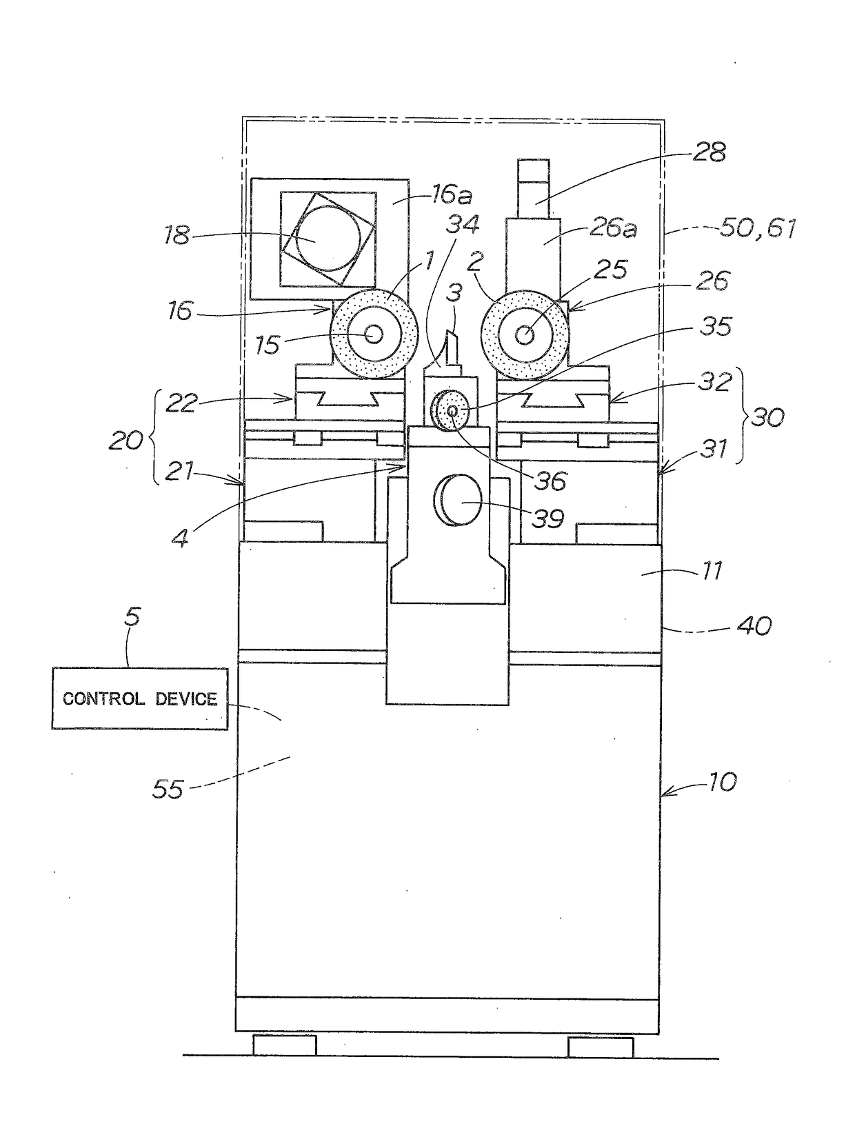
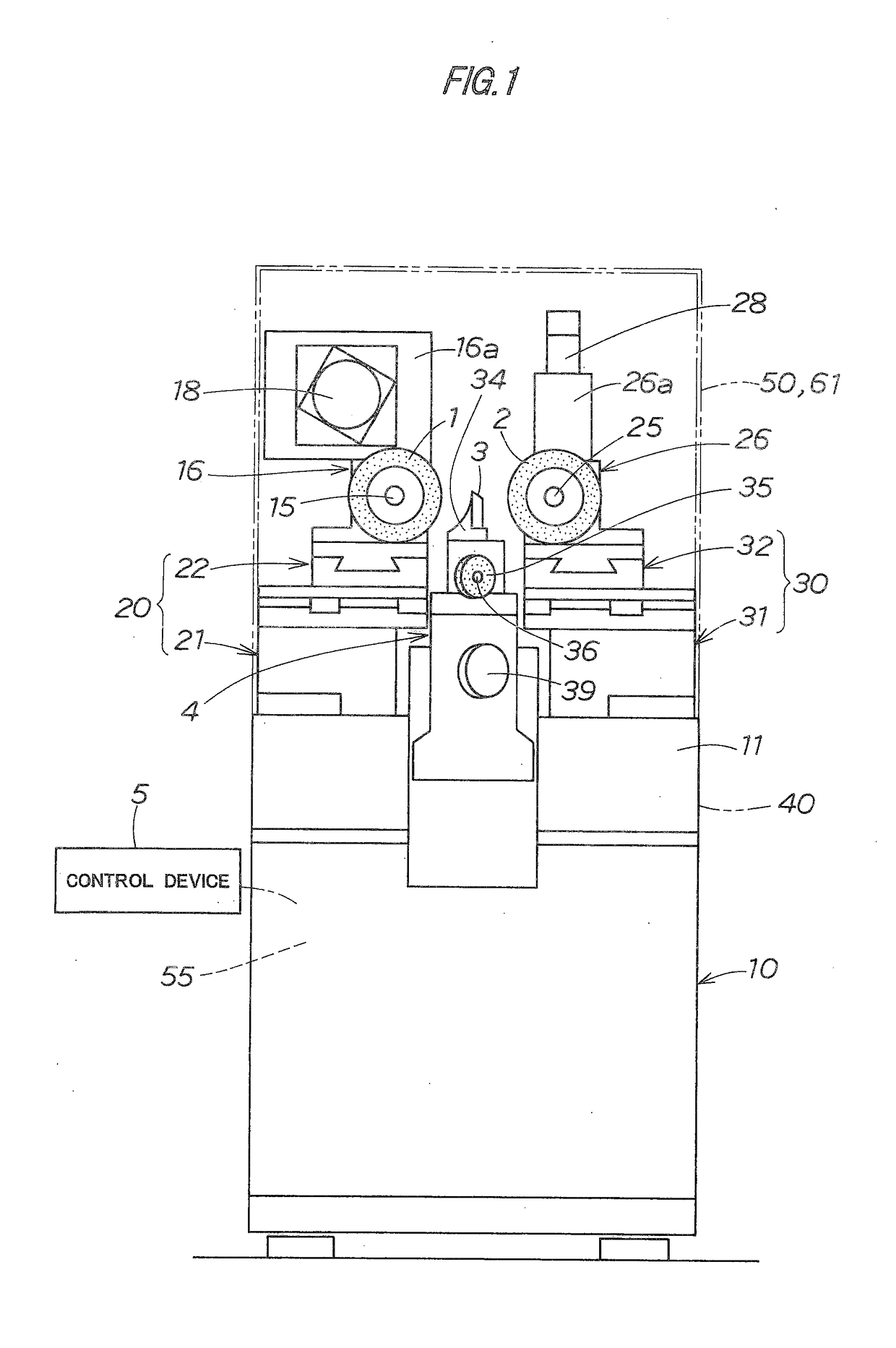
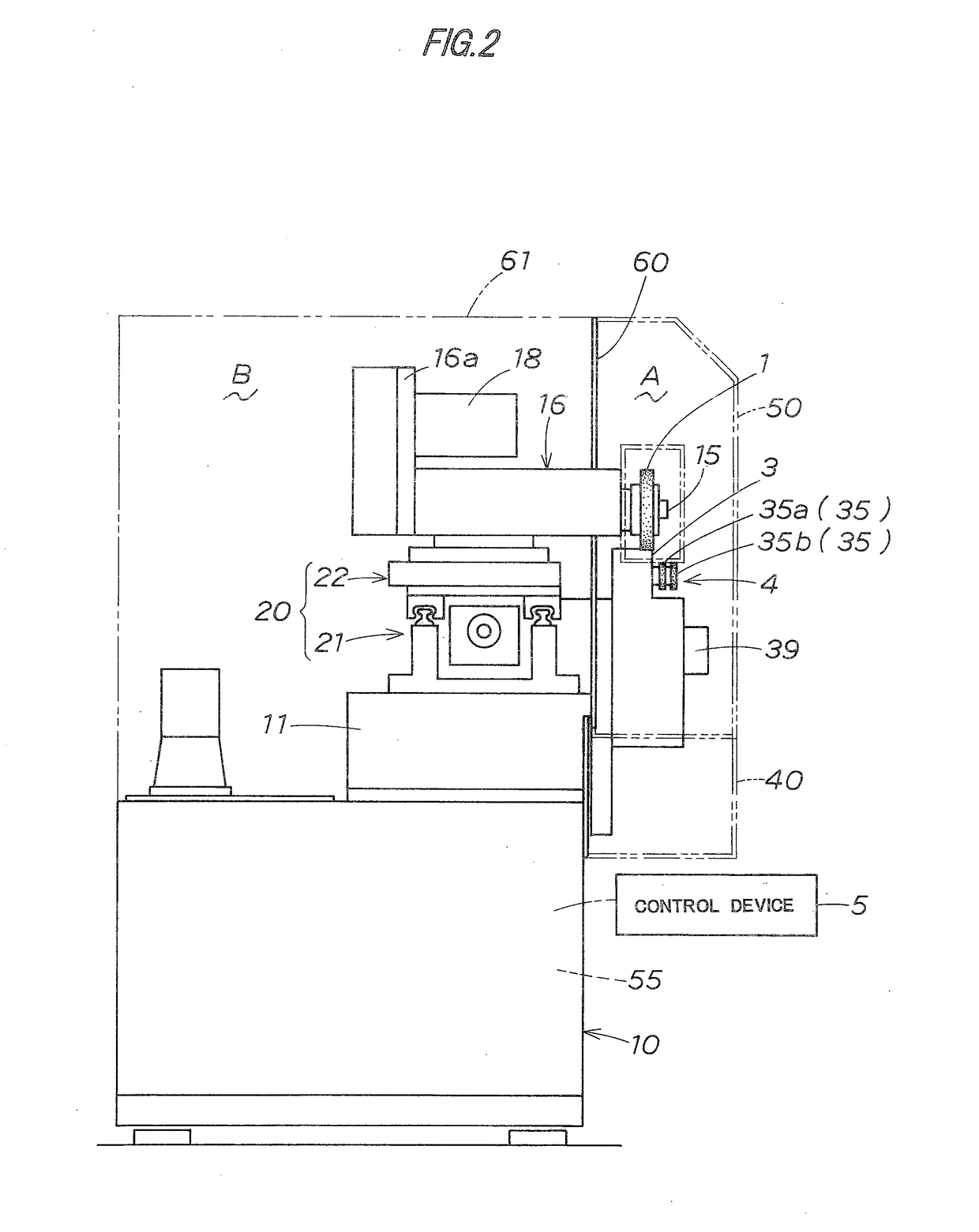
[0047]FIGS. 1 to 6 show a centerless grinding machine of the present invention. The grinding machine is a small centerless grinding machine that includes a space-saving structure for executing centerless grinding of the periphery of work W. Specifically, the machine is configured with a desktop size mountable on an office desk or the like.

[0048]In the specific configuration of the grinding machine, main elements are grinding wheel 1, regulating wheel 2, blade 3, dressing unit 4 and control device 5. These main elements and peripheral elements each have a space-saving structure.

[0049]In the grinding machine, first, bed 11 is fixed on machine pedestal 10. Component units disposed on the bed 11 include grinding wheel spindle case 16 provided with the grinding wheel 1, regulating w...


PUM


Abstract

A space-saving centerless grinding machine having high operability is obtained by devising the configuration of component units around the basic configuration of the machine. A dressing means for performing a dressing process for a grinding wheel and a regulating wheel comprises a single dressing unit. The dressing unit is located at a lower position between the grinding wheel and the regulating wheel, and thus eliminates the need for right and left dresser spaces for grinding wheels that have most seriously affected the breadthwise dimension of a conventional centerless grinding machine, leading to space saving and a considerable reduction in the breadthwise dimension of the centerless grinding machine.

Description

BACKGROUND OF THE INVENTION[0001]Field of the Invention[0002]The present invention relates to a centerless grinding machine and more particularly to a centerless grinding machine suited to be used in a small installation space in particular.[0003]Description of the Related Art[0004]A centerless grinding machine is, as shown in FIG. 7, basically configured in that the periphery of work piece (hereinafter called work) W is ground by grinding wheel (c) rotationally driven while work W is rotationally supported by regulating wheel (a) and blade (b), and the regulating wheel (a) and the grinding wheel (c) are disposed opposite to each other at either side of work W (refer to Japanese Laid-Open Patent 2004-114179).[0005]Also, the regulating wheel (a) and the grinding wheel (c) are respectively provided with dressing units (d), (e) for dressing the grinding surface, and both of dressing units (d), (e) are disposed at the right and left sides of the regulating wheel (a) and the grinding whe...

Claims


Application Information

Patent Timeline
Patent Type & Authority Applications(United States)
IPC IPC(8): B24B5/26B24B51/00B24B53/007
CPCB24B5/26B24B51/00B24B53/007B24B5/22B24B5/30B24B5/35B24B53/053B24B55/02B24B41/02B24B49/18B24B53/003B24B53/04B24B53/047
Inventor SASAKURA, SHIZUKIWAKAYAMA, NAOHIKO
Owner KOYO MASCH IND CO LTD
Why Eureka
Try Eureka