Control system of internal combustion engine

Inactive Publication Date: 2017-04-20
TOYOTA JIDOSHA KK
View PDF16 Cites 1 Cited by
  • Summary
  • Abstract
  • Description
  • Claims
  • Application Information

AI Technical Summary

Benefits of technology

[0019]According to this, the air-fuel mixture which contains the fuel flowing again to the insides of the cylinders after being blown back to the inside of the intake passage in a part of the cylinders is kept from being burned. As a result, flow of high temperature exhaust gas in the exhaust passage is suppressed, therefore occurrence of “after fire” due to the air-fuel mixture which did not completely burn, but flowed into the exhaust passage can be suppressed.

Problems solved by technology

However, in the conventional system, if the closing timing of the intake valve becomes after intake bottom dead center in order to perform the Atkinson cycle, after the fuel injected during the intake stroke once flows into the cylinder, it is blown back to the inside of the intake port in a period after intake bottom dead center where the intake valve is open.
As a result, the air-fuel mixture containing the fuel which again flowed into the cylinder during the fuel cut control is liable to not completely burn during the fuel cut control, but end up blowing through to the inside of the exhaust passage as unburned gas.

Method used


Image

  • Control system of internal combustion engine
  • Control system of internal combustion engine
  • Control system of internal combustion engine

Examples


Embodiment Construction

[0026]Below, the “control system of an internal combustion engine according to the present invention” (below, sometimes referred to as the “present control system”) will be explained with reference to the drawings.

[0027][Schematic Configuration]

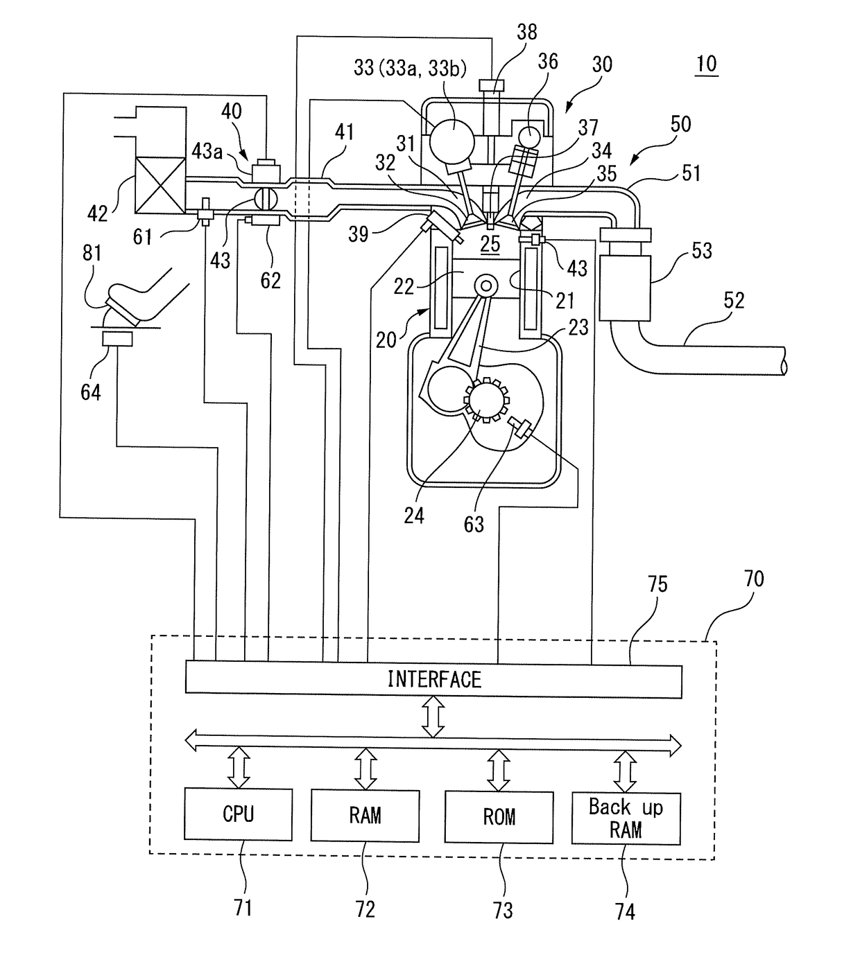
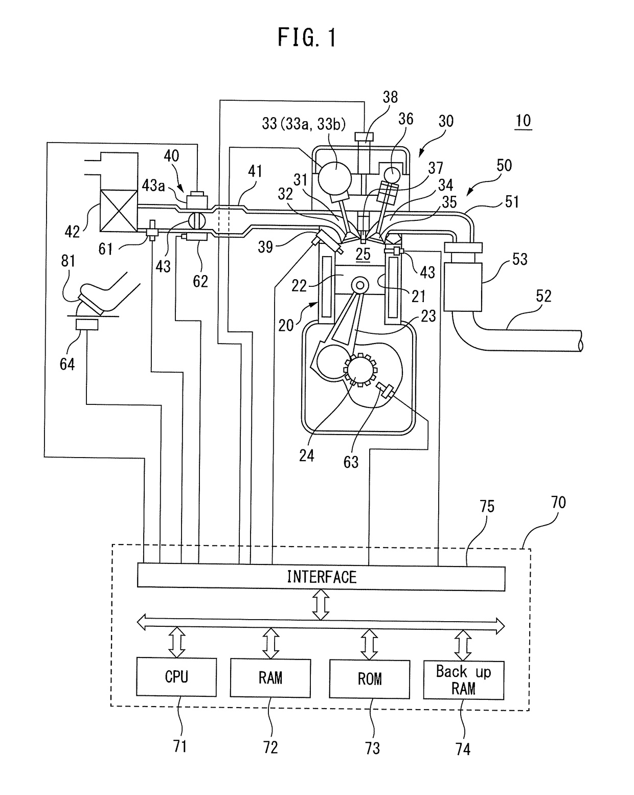
[0028]The control system according to an embodiment of the present invention (below, referred to as the “present control system”) is applied to a spark ignition type multi-cylinder internal combustion engine 10 (below, referred to as the “engine”) shown in FIG. 1. Note that, FIG. 1 shows only the cross-section of a specific cylinder, but other cylinders are provided with the same configuration as well.

[0029]This engine 10 includes a cylinder block 20, a cylinder head 30 fixed on the cylinder block 20, an intake system 40 for supplying air to the cylinder block 20, and an exhaust system 50 for discharging the exhaust gas from the cylinder block 20 to the outside.

[0030]The cylinder block 20 includes a cylinder 21, a piston 22, a connecting rod ...


PUM


Abstract

A control system according to one aspect of the present invention is applied to an engine. The engine comprises a cylinder injector and an intake valve driving device capable of changing the closing timing of an intake valve. If the execution condition is satisfied when the injection timing of fuel of the cylinder injector is before intake bottom dead center and an Atkinson cycle is carried out, the engine delays the injection timing of the fuel of the cylinder injector to a time after intake bottom dead center, injects the fuel, then executes fuel cut control.

Description

TECHNICAL FIELD[0001]The present invention relates to a control system of an internal combustion engine comprising an intake valve driving device capable of changing a closing timing of an intake valve.BACKGROUND ART[0002]Known in the past has been a control system of a spark-ignition type internal combustion engine which comprises an intake port injector injecting fuel into an intake port and an intake valve driving device capable of changing a closing timing of the intake valve, and performs an Atkinson cycle improving an engine efficiency by making an expansion ratio larger compared with a compression ratio (for example, see PLT 1).[0003]The system disclosed in PLT 1 (Below, referred to as the “conventional system”) is configured to set the closing timing of the intake valve to a time after intake bottom dead center and push back a part of the air once taken into a cylinder to the inside of the intake port so as to delay the compression start timing. Accordingly, in the conventio...

Claims


Application Information

Patent Timeline
Patent Type & Authority Applications(United States)
IPC IPC(8): F02D37/02F02D41/30F02P5/145F02D41/40
CPCF02D37/02F02P5/145F02D41/3005F02D41/401F02D41/10F02D41/123F02D13/0269F02D2041/001F02P5/045F02P9/005F02P11/02Y02T10/12Y02T10/40
Inventor NAKASAKA, YUKIHIRO
Owner TOYOTA JIDOSHA KK
Why Eureka
Try Eureka