
Apparatuses and Methods for Determining Permittivity in Downhole Locations

a technology for determining permittivity and downhole locations, applied in the field of log data processing methods and apparatuses, can solve problems such as difficult to achieve reliably or in a reasonable timescale, specific problems can arise, and imperfect sinusoids are difficult to interpret correctly, so as to improve the presentation of edge, bed and layer features

Inactive Publication Date: 2017-04-20
REEVES WIRELINE TECH
View PDF0 Cites 4 Cited by
  • Summary
  • Abstract
  • Description
  • Claims
  • Application Information

AI Technical Summary

Benefits of technology

This patent describes a method for generating three-dimensional images of rock formations in a borehole. By using data from a drilling rig, the method can create realistic and accurate images that show the features of the rock and how they are related to each other. This makes it easier for geologists to interpret and assess the quality of the rock. The method also allows users to adjust the sensitivity of the interpretation based on the information they are getting. Overall, this method provides a better way to understand and analyze the geology of a borehole.

Problems solved by technology

In the logging of oil, coal and gas fields (including fields combined with rock types such as shales) specific problems can arise.
This leads to various complications associated with determining geological attributes of the oil or gas field in question.
These can represent fractures, beds, the edges of beds and similar phenomena that either may help to indicate the likely presence of materials of value; or may indicate potential problems in the extraction of such materials.
Such imperfect sinusoids are hard to interpret correctly and yet are commonplace.
This is difficult to achieve reliably or in a reasonable timescale.
Most machine viewers are also likely to be inefficient at identifying the sinusoids.
This results in a confusing superimposition of one sinusoid on another in the two-dimensional image log.
Neither machine viewers nor humans are very good at discriminating between different features in such conditions.
Some of the sinusoids are geologically more significant than others, yet hitherto machine-based viewing methods have been poor at discriminating between important and insignificant features.
Prior art image logging methods are not capable of interpolating to produce data on the approximately cylindrical region of rock that is removed during the process of drilling or otherwise forming the borehole.
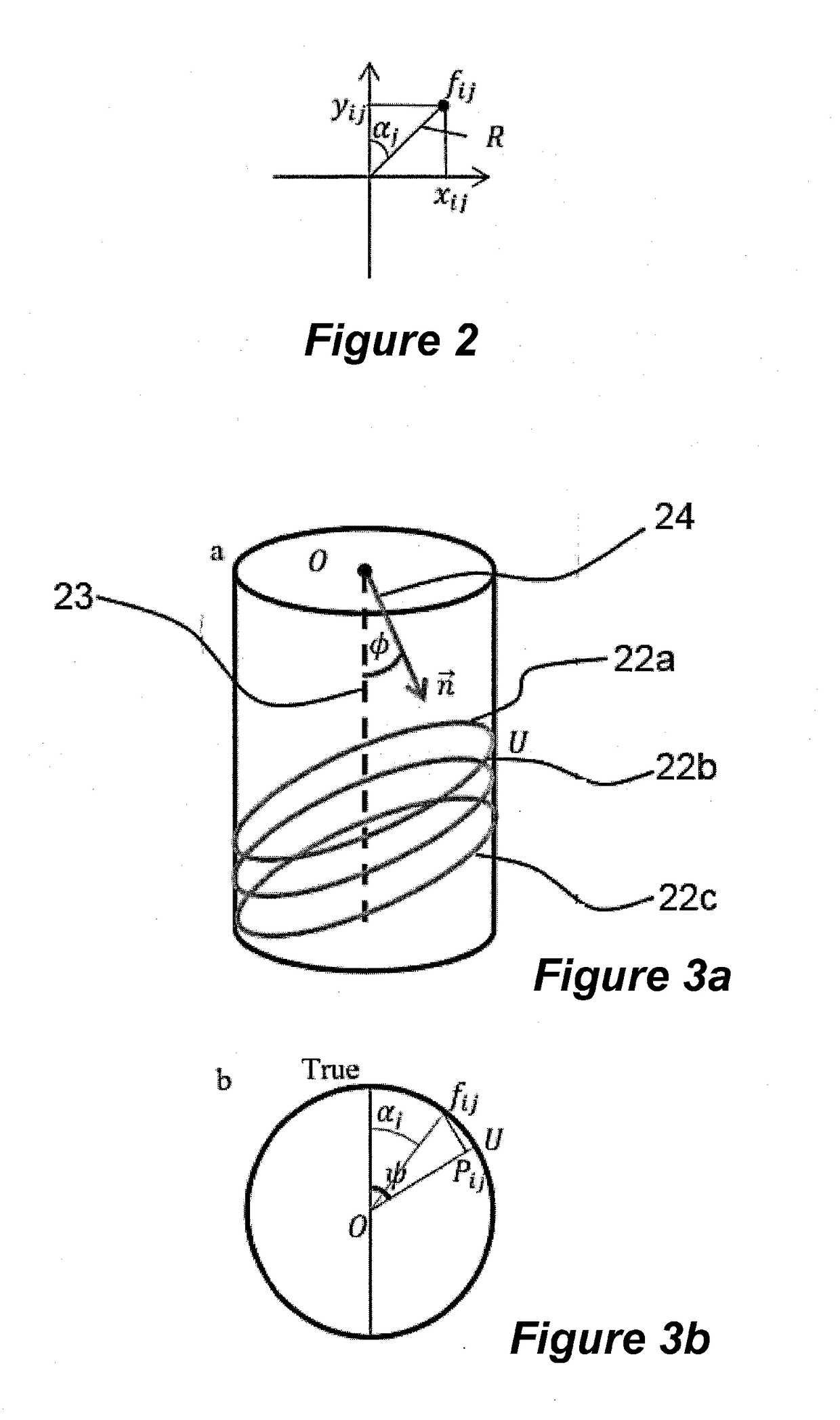
Moreover the prior art has not provided any good way of synthesizing images of cores, i.e. discrete cylindrical or essentially cylindrical sections of rock used e.g. for assessing various qualities of the rock in which a borehole is to be drilled or has been drilled.

Method used


Image

  • Apparatuses and Methods for Determining Permittivity in Downhole Locations
  • Apparatuses and Methods for Determining Permittivity in Downhole Locations
  • Apparatuses and Methods for Determining Permittivity in Downhole Locations

Examples


Embodiment Construction

[0082]There now follows a description of preferred embodiments of the present disclosure, by way of non-limiting example.

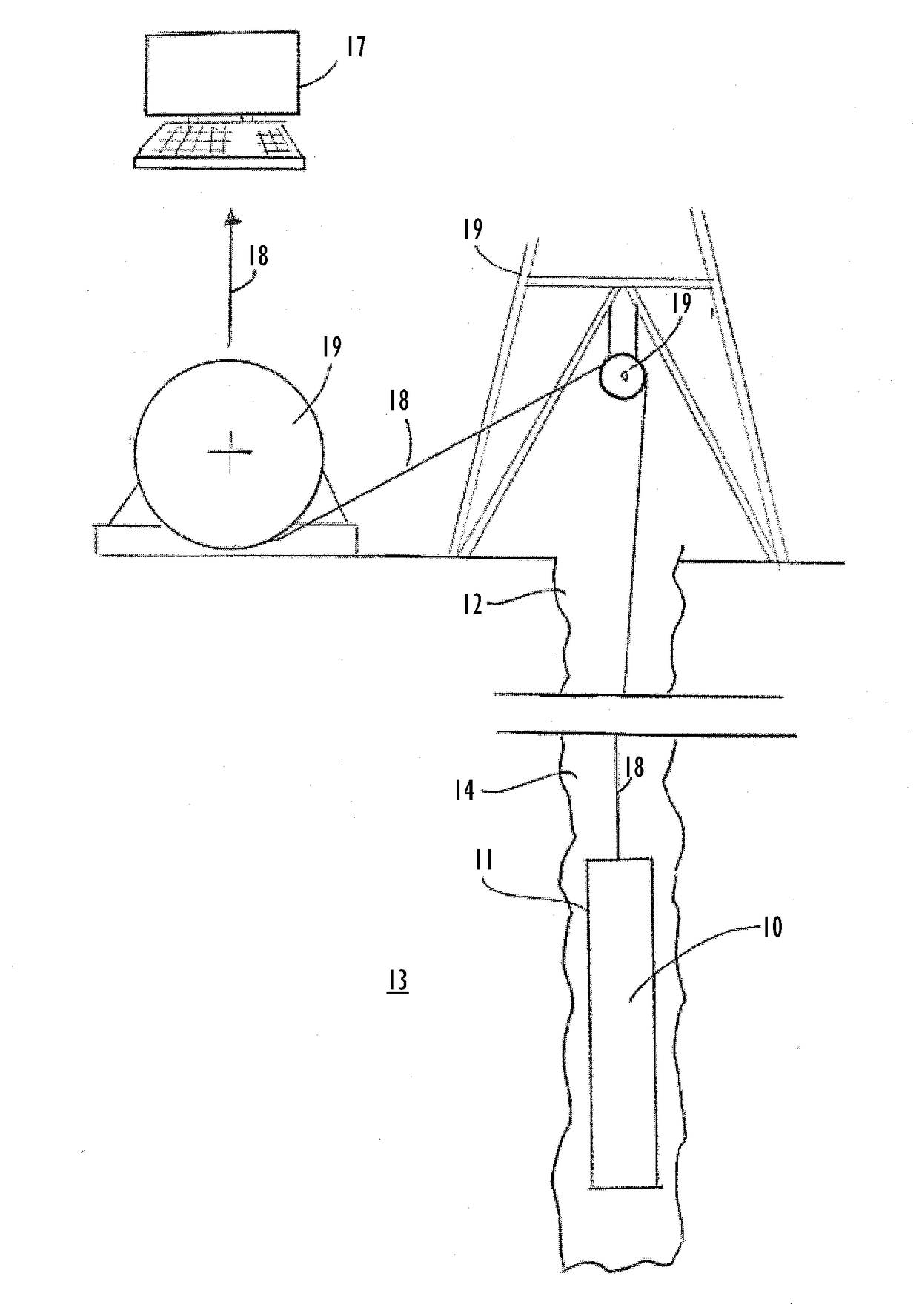
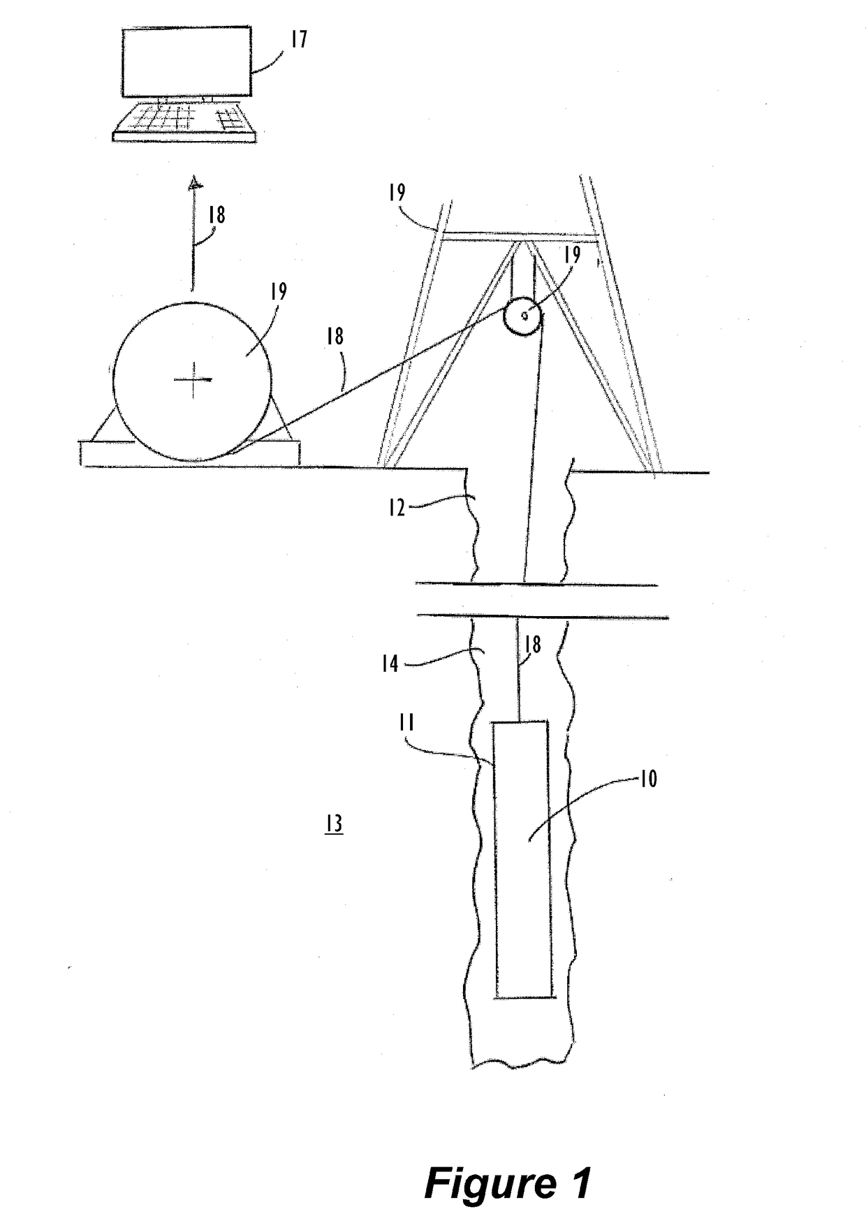
[0083]Referring to FIG. 1 of the drawings there is shown a borehole 12 formed in e.g. a hydrocarbon-bearing rock 13 by drilling. In FIG. 1 an imaging logging tool 10 according to the present disclosure is deployed in the borehole 12 and operatively connected, or at least is connectable, to communicate with a programmable device that in the embodiment shown takes the form of a personal computer 17 (although other forms of programmable device are possible within the scope of the present disclosure). FIG. 1 shows the logging tool 10 connected to the computer 17 by wireline 18 that is paid out into the borehole 12 by way of per se known paying out and rewinding equipment 19.

[0084]The logging tool 10 may be e.g. a resistivity image logging tool, the essential characteristics of which are known to the person of skill in the art; an acoustic logging tool, with which the ...


PUM


Abstract

To process geological log data, a two-dimensional set of log values recorded at a plurality of points is obtained about a borehole periphery, and over a chosen length along the borehole. The set of log values are decomposed by identifying in the set one or more main functions indicative of one or more main geological layer features of the rock penetrated by the borehole and removing log values corresponding to values of the main functions from the set of log values. Further decomposing the set of log values can be performed, as necessary iteratively, based on one or more subsidiary functions. The log values of the set remaining after identification and removal of values are designated as texture. Functions indicative of the main and subsidiary layer features and the texture are used to construct a synthesised volume representing the rock removed during creation of the chosen length of the borehole.

Description

FIELD OF THE DISCLOSURE[0001]The subject matter of the present disclosure relates to a method of and apparatus for processing log data, especially image log data. The disclosed subject matter also relates to images, logs, and data produced in accordance with the methods and using the apparatuses defined herein.BACKGROUND OF THE DISCLOSURE[0002]As is well known, prospecting for minerals of commercial or other value (including but not limited to hydrocarbons in liquid or gaseous form; water e.g. in aquifers; and various solids used e.g. as fuels, ores or in manufacturing) is economically an extremely important activity. For various reasons those wishing to extract such minerals from below the surface of the ground or the floor of an ocean need to acquire as much information as possible about both the potential commercial worth of the minerals in a geological formation and also any difficulties that may arise in the extraction of the minerals to surface locations at which they may be u...

Claims


Application Information

Patent Timeline
Patent Type & Authority Applications(United States)
IPC IPC(8): G01V1/48E21B47/12
CPCG01V1/48E21B47/12G01V2210/48G01V2210/6169G01V2210/614G01V2210/62G01V1/325G01V1/34G01V3/38G01V3/18G01V5/04G01V11/00
Inventor GORBAN, ALEXANDERMIRKES, EVGENYLEVESLEY, JEREMYWHETTON, JAMES
Owner REEVES WIRELINE TECH
Learn More