
Dynamic transaction card antenna mounting

a technology of dynamic transaction and antenna, applied in the field of dynamic transaction cards, can solve the problem of occupying a significant amount of space for antennas

Active Publication Date: 2017-04-20
CAPITAL ONE SERVICES
View PDF9 Cites 26 Cited by
  • Summary
  • Abstract
  • Description
  • Claims
  • Application Information

AI Technical Summary

Benefits of technology

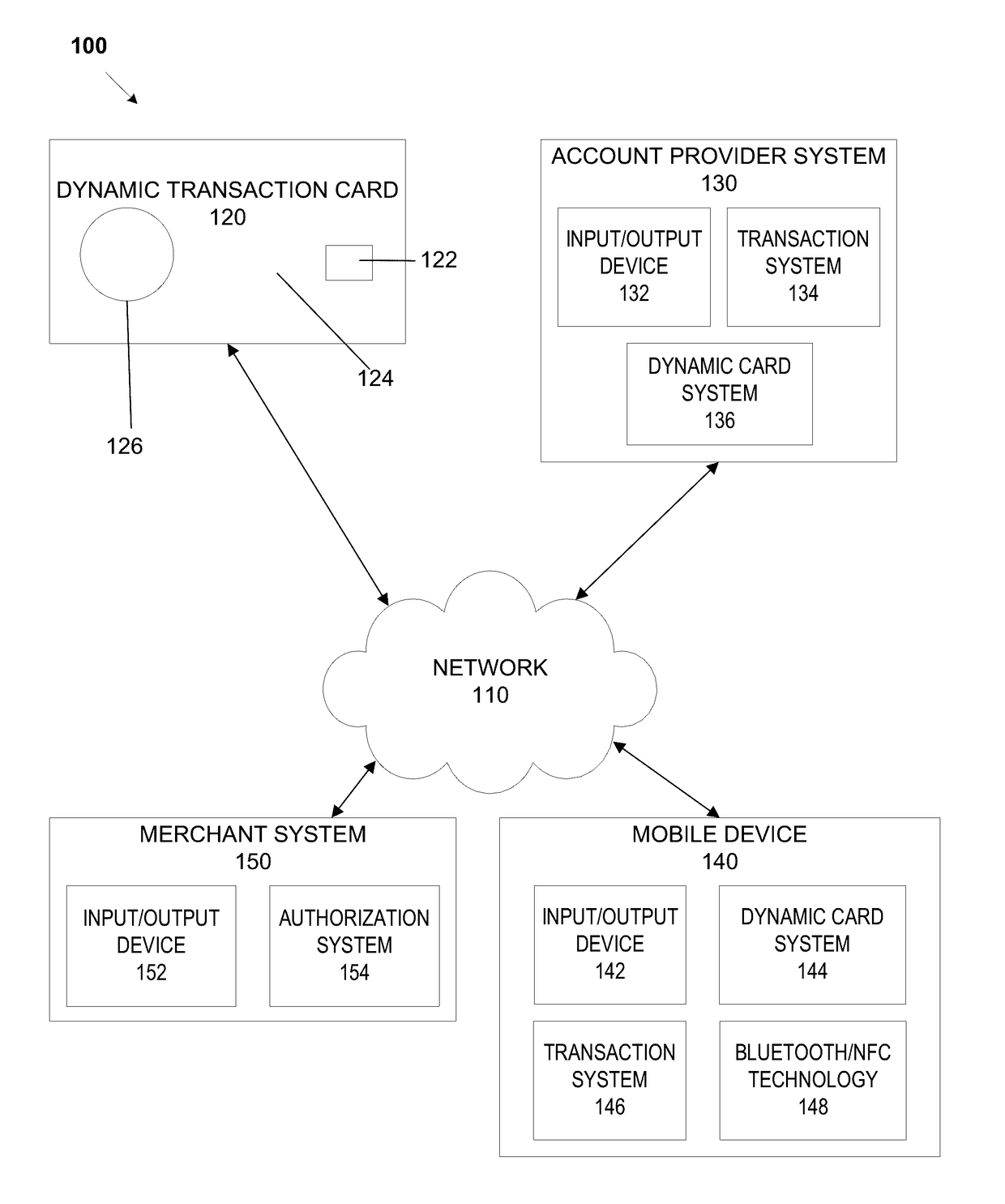
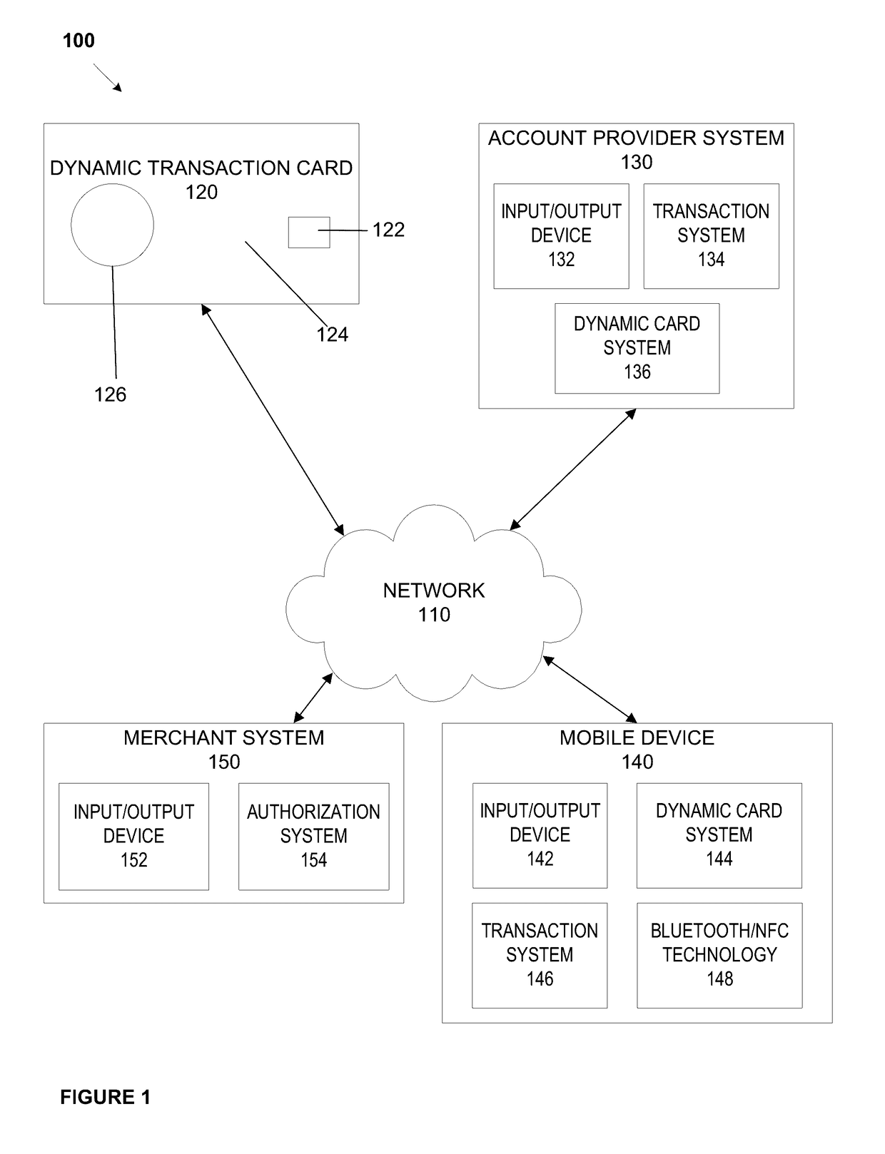
The patent describes a dynamic transaction card that can be used to make purchases and view account information. The card has layers of printed circuit assemblies and plastic support scaffolding that create a smooth surface. The card can be powered up and connected to a mobile device, which will request updated account information from the card's financial institution. The mobile device is securely connected to the financial institution's system, allowing for a secure purchase and connection between the card and the bank.

Problems solved by technology

The antennas take up a significant amount of space on a smart card PCB that could be used for other components, additional functionality or design alternatives, such as display orientation, display size, and greater battery size.

Method used


Image

  • Dynamic transaction card antenna mounting
  • Dynamic transaction card antenna mounting
  • Dynamic transaction card antenna mounting

Examples


Embodiment Construction

[0043]The entire contents of the following applications are incorporated herein by reference: U.S. Provisional Application No. 62 / 266,324 entitled “Printed Circuit Board with Integrated Battery” filed Dec. 11, 2015; U.S. Provisional Application No. 62 / 270,307 entitled “Capacitive Powertrain for a Smart Card” filed Dec. 21, 2015; U.S. Provisional Application No. 62 / 305,599 entitled “Smart Card EuroPay Master Card Visa (“EMV”) Terminal Energy Harvesting” filed Mar. 9, 2016; U.S. patent application Ser. No. 14 / 977,730 entitled “A System, Method, and Apparatus for Locating a Bluetooth Enabled Transaction Card, filed Dec. 22, 2015, which claims the benefit of U.S. Provisional Application No. 62 / 095,190, filed on Dec. 22, 2014; U.S. Pat. No. 9,105,025, entitled, Enhanced Near Field Communications Attachment filed on May 29, 2014, which claims the benefit of U.S. Provisional Application No. 61 / 570,275 filed on Dec. 13, 2011 and U.S. Provisional Application No. 61 / 547,910 filed on Oct. 17, ...


PUM


Abstract

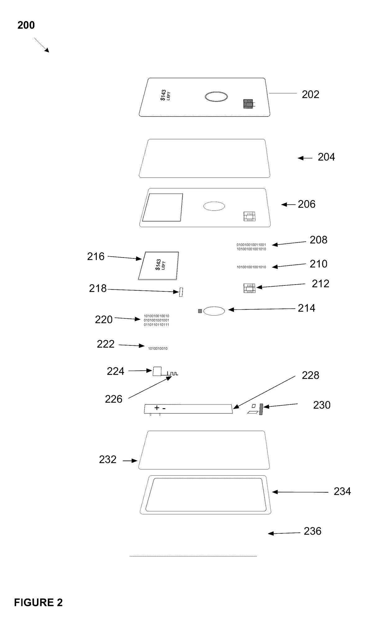
A dynamic transaction card that includes a transaction card having a number of layers, each of which may be interconnected to one another. For example, a dynamic transaction card may include an outer protective layer, a core layer, a potting layer, a touch sensor layer, a display layer (including, for example, LEDs, a dot matrix display, and the like), a microcontroller storing firmware, Java applets, Java applet integration, and the like, an EMV™ chip, an energy storage component, one or more antennas (e.g., Bluetooth™ antenna, NFC antenna, and the like), a power management component, a flexible printed circuit board (PCB), a chassis, and / or a card backing layer, which may include a back protective layer. The antennas may be mounted on the protective layers, which may be laminated to the core layer, and connected to the core layer onto a printed circuit board (PCB) using conductive epoxies.

Description

CROSS REFERENCE TO RELATED APPLICATIONS[0001]The present application is a continuation-in-part of U.S. patent application Ser. No. 15 / 098,585, filed Apr. 14, 2016, which claims the benefit of U.S. Provisional Application No. 62 / 147,568 entitled “A System, Method, and Apparatus for a Dynamic Transaction Card” filed Apr. 14, 2015; and U.S. Provisional Application No. 62 / 270,669 entitled “A System, Method, and Apparatus for a Dynamic Transaction Card” filed Dec. 22, 2015. The entire contents of these applications are incorporated herein by reference.FIELD OF THE DISCLOSURE[0002]The present disclosure relates to a dynamic transaction card with antennas mounted on the protective layers of the dynamic transaction card to avoid the necessity of the antennas being implemented as traces on the main printed circuit board (PCB).BACKGROUND OF THE DISCLOSURE[0003]Smart cards using EMV™ technology may receive data from, for example, a mobile device in connection with the dynamic transaction card ...

Claims


Application Information

Patent Timeline
IPC IPC(8): G06K19/077G06K19/02G06K19/04
CPCG06K19/07722G06K19/045G06Q20/34G06K19/07733G06K19/07773G06K19/02G06Q20/341G06Q20/352G06Q20/354G06Q20/3552G06Q20/4016G06Q20/405G06K19/07707G06Q20/321
Inventor WURMFELD, DAVIDLOCKE, TYLERMARKSON, THEODOREKOEPPEL, ADAM
Owner CAPITAL ONE SERVICES
Learn More