Optically connectable controller using passive optical devices

a technology of optical devices and connectable controllers, applied in the direction of fiber transmission, electromagnetic networks, electromagnetic networks of bus-type type, etc., can solve the problems of data loss probability very significant, data receiving side cannot become aware, and data transmission would be very slow, etc., to achieve the effect of simple structur

Inactive Publication Date: 2017-04-20
HYUNDAI INFRACORE
View PDF1 Cites 1 Cited by
  • Summary
  • Abstract
  • Description
  • Claims
  • Application Information

AI Technical Summary

Benefits of technology

[0012]At least one embodiment of the present invention is directed to the provision of an optical connectable controller using passive optical devices, which has a simple structure and is inexpensive.

Problems solved by technology

However, in both of the EIA-485 / 422 standards, only one device can exclusively occupy a communication line at one time.
In such cases, transmitting data to or from peripheral devices would be very slow as a matter of fact, and the probability of data loss becomes very significant.
In particular, for data loss, a device that sent data cannot become aware of whether data get lost, and a data receiving side cannot become aware of the fact itself that data is sent.
Accordingly, re-transmission is impossible and the reliability of a system may be significantly degraded.
In particular, in systems in which real-time propriety and reliability are very important, such as fire alarm systems or burglar alarm systems, slow speed due to the configuration of a large scale network and poor reliability attributable to loss of data are critical problems.

Method used


Image

  • Optically connectable controller using passive optical devices
  • Optically connectable controller using passive optical devices
  • Optically connectable controller using passive optical devices

Examples


Embodiment Construction

[0026]With regard to embodiments of the present invention disclosed herein, specific structural and functional descriptions are given merely for the purpose of illustrating the embodiments of the present invention. Embodiments of the present invention may be practiced in various forms, and the present invention should not be construed as being limited to the embodiments disclosed herein.

[0027]Embodiments of the present invention will be described in detail below with reference to the accompanying drawings. The same reference numerals will be used to denote the same components throughout the accompanying drawings, and redundant descriptions of the same components will be omitted.

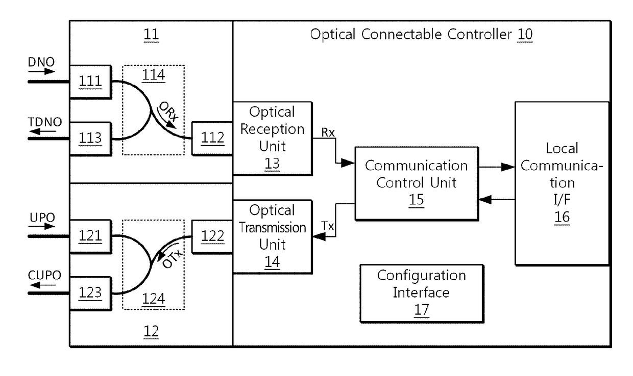
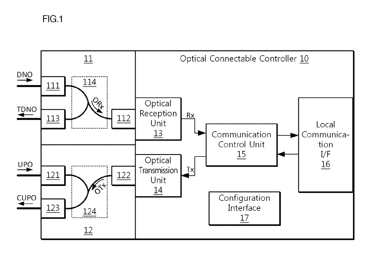
[0028]FIG. 1 is a conceptual diagram illustrating an optical connectable controller 10 according to an embodiment of the present invention.

[0029]Referring to FIG. 1, the optical connectable controller 10 may include an optical splitter 11, an optical combiner 12, an optical reception unit 13, an optical trans...


PUM


Abstract

An optical connectable controller is disclosed. The optical connectable controller includes an optical splitter, an optical combiner, an optical reception unit, an optical transmission unit, and a communication control unit. The optical splitter splits an optically received downstream optical signal into a branch optical signal and a pass-through optical signal. The optical combiner optically combines an outgoing optical signal and an upstream optical signal into a combined upstream optical signal. The optical reception unit receives the branch optical signal, and converts the branch optical signal into an incoming electric signal to be transferred to the communication control unit. The optical transmission unit receives the outgoing electric signal, and converts the outgoing electric signal into the outgoing optical signal. The communication control unit extracts an address, outputs control commands or data or discards the incoming electric signal, generates the outgoing electric signal, and outputs the outgoing electric is signal.

Description

CROSS-REFERENCE TO RELATED APPLICATIONS[0001]This application claims the benefit under 35 USC 119(a) of Korean Patent Application No. 10-2014-0045849 filed on Apr. 17, 2014 in the Korean Intellectual Property Office, the entire disclosure of which is incorporated herein by reference for all purposes.BACKGROUND[0002]Field[0003]The present invention relates to an optical connectable controller.[0004]Description of Related Art[0005]The conventional EIA-485 / 422 telecommunication standards have been widely used as telecommunication standards for 1:N or N:N digital communication. The EIA-485 / 422 standards use differential signals, and thus they are robust to noise and can support high-speed data communication even over a relatively long distance, for example, about 1.5 Km. The EIA-485 standard uses a half-duplex method using two wire transmission lines, and enables only transmission or reception at a moment. In contrast, the EIA-422 standard uses a full-duplex method using four wire trans...

Claims


Application Information

Patent Timeline
Patent Type & Authority Applications(United States)
IPC IPC(8): H04Q11/00H04L5/14
CPCH04Q11/0003H04L5/14H04Q2011/0049H04Q2011/0015H04Q2011/0033H04Q11/0067H04B10/278H04L5/16H04B10/2589
Inventor YANG, JONG SEOG
Owner HYUNDAI INFRACORE
Why Eureka
Try Eureka