Alignment rectifying device

Inactive Publication Date: 2017-04-27
MAJOR SHAWN
View PDF0 Cites 26 Cited by
  • Summary
  • Abstract
  • Description
  • Claims
  • Application Information

AI Technical Summary

Benefits of technology

[0004]The alignment rectifying device for rectifying a joint between two pipes comprises a central hub, multiple plunger-cylinder assemblies, and a curved plate member. Each plunger-cylinder assembly comprises a plunger portion in sliding communication within a cylinder portion, where each plunger-cylinder assembly outspreads radially from the central hub, each plunger-cylinder assembly actuated by a hydraulic pump positioned within the hub to radially extend the plunger

Problems solved by technology

The welded joints between consecutive units of pipe characteristically need to be of superior quality and reliability, because underwater pipelines are characteristically exposed to cyclic loading both during and after the installation or commissioning process, giving an increased risk of failing of the joints because of the fatigue loading during the aforementioned cycle.
Misalignment of the ends of pipes during the welding process of a joint can adversely affect the quality of the weld generated.
Such mis

Method used


Image

  • Alignment rectifying device
  • Alignment rectifying device
  • Alignment rectifying device

Examples


Embodiment Construction

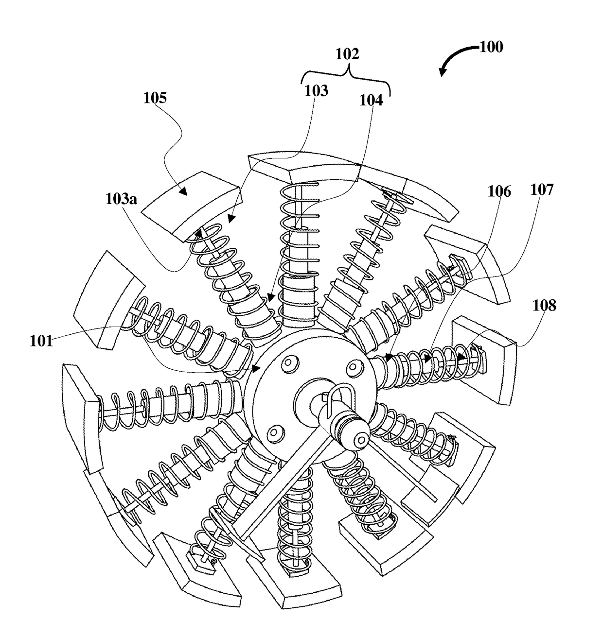
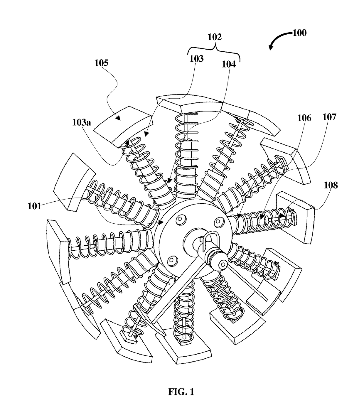
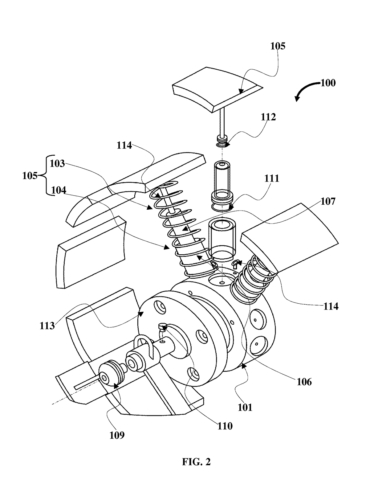
[0011]FIG. 1 exemplarily illustrates a front perspective view of the alignment rectifying device 100. The alignment rectifying device 100 for rectifying a joint between two pipes comprises a central hub 101, multiple plunger-cylinder assemblies 102, and a curved plate member 105. Each plunger-cylinder assembly 102 comprises a plunger portion 103 in sliding communication within a cylinder portion 104, where each plunger-cylinder assembly 102 outspreads radially from the central hub 101, each plunger-cylinder assembly 102 actuated by a hydraulic pump positioned within the central hub 101 to radially extend the plunger portion 103 of the plunger-cylinder assembly 102. The curved plate member 105 is positioned at the distal end 103a of the plunger portion 103 each plunger-cylinder assembly 102, where the curved plate member 105 is configured to contact a surface of joint between two pipes internally, where each curved plate member 105 actuated by the hydraulic pump applies pressure on t...


PUM


Abstract

An alignment rectifying device for a rectifying a joint between two joint between two pipes includes a central hub, multiple plunger-cylinder assemblies, and a curved plate member. Each plunger-cylinder assembly comprises a plunger portion in sliding communication within a cylinder portion, where each plunger-cylinder assembly outspreads radially from the central hub, each plunger-cylinder assembly actuated by a hydraulic pump positioned within the hub to radially extend the plunger portion of the plunger-cylinder assembly. The curved plate member is positioned at the distal end of the plunger portion each plunger-cylinder assembly, where the curved plate member is configured to contact a surface of joint between two pipes internally, where each curved plate member actuated by the hydraulic pump applies pressure on the joint to rectify misalignment at the joint.

Description

BACKGROUND[0001]During the process of laying a pipe line, for example, an oil pipeline, it is normally essential to weld a sector of pipe to an end of the pipeline. The pipeline may be aligned and laid under a water body such as sea. The welded joints between consecutive units of pipe characteristically need to be of superior quality and reliability, because underwater pipelines are characteristically exposed to cyclic loading both during and after the installation or commissioning process, giving an increased risk of failing of the joints because of the fatigue loading during the aforementioned cycle. Misalignment of the ends of pipes during the welding process of a joint can adversely affect the quality of the weld generated. The precise welding of two pipe ends is therefore of primary importance. Subsequently, it is necessary to measure the amount of misalignment before and / or after the welding process.[0002]Such misalignment, or Hi-Lo as generally known in piping industry, is a ...

Claims


Application Information

Patent Timeline
IPC IPC(8): B23K37/053F16L9/02F16L13/02
CPCB23K37/0531F16L9/02F16L13/02F16L1/20
Inventor MAJOR, SHAWN
Owner MAJOR SHAWN
Why Eureka
Try Eureka