A passenger aircraft with a downwardly foldable wing tip device

a technology of wing tip and passenger aircraft, which is applied in the direction of aircraft control, wing adjustment, aircraft components, etc., can solve the problems of wing tip being liable to fold upwards, heavy actuators and/or locking mechanisms, and effectively limited maximum aircraft span, etc., to reduce the required capacity of actuators

Active Publication Date: 2017-04-27
AIRBUS OPERATIONS LTD
View PDF0 Cites 7 Cited by
  • Summary
  • Abstract
  • Description
  • Claims
  • Application Information

AI Technical Summary

Benefits of technology

[0015]Such an arrangement is beneficial because it reduces the required capacity of an actuator to move the wing tip device from the ground configuration to the flight configuration. In some embodiments it may even reduce the need for an actuator all together.

Problems solved by technology

However, the maximum aircraft span is effectively limited by airport operating rules which govern various clearances required when manoeuvring around the airport (such as the span and / or ground clearance required for gate entry and safe taxiway usage).
However, a disadvantage with such arrangements is that they tend to require heavy actuators and / or locking mechanisms to deploy the wing and to securely hold it in the flight configuration.
Another disadvantage in upwardly folding wings is that the aerodynamic lift forces on the wing during use, tend to be urging the wing towards the folded position.
Thus, in the theoretical event of an equipment failure (for example an actuator or lock failure) the wing may be liable to fold upwards.
Even if safety systems are in place to prevent this, there may at least be an adverse passenger perception of such a possibility occurring.

Method used


Image

  • A passenger aircraft with a downwardly foldable wing tip device
  • A passenger aircraft with a downwardly foldable wing tip device
  • A passenger aircraft with a downwardly foldable wing tip device

Examples


Embodiment Construction

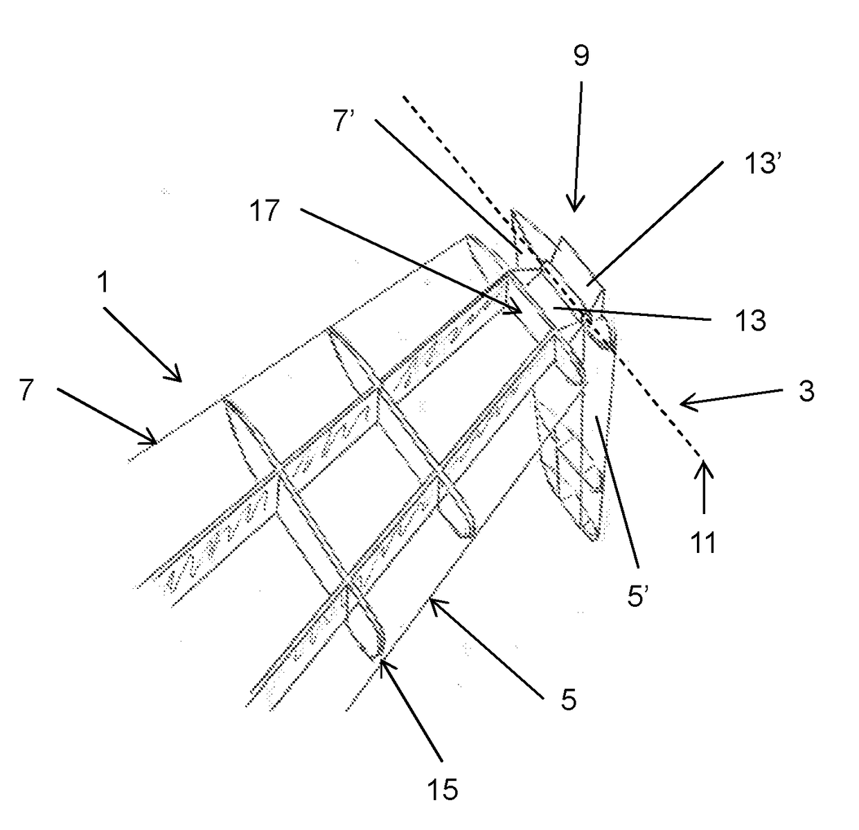
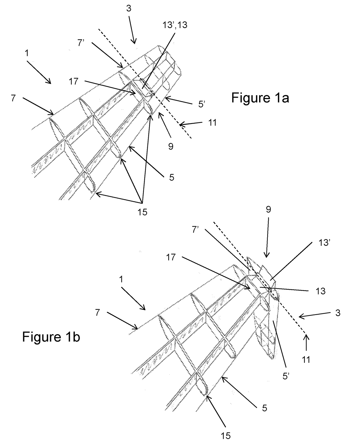
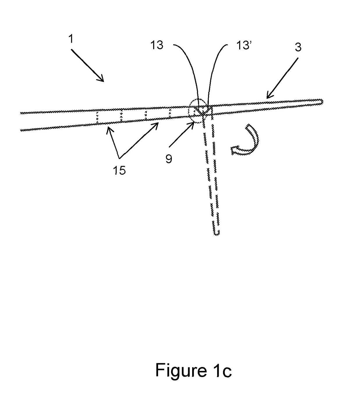
[0036]FIGS. 1a and 1b are perspective views of part of a wing 1 of a passenger aircraft (see FIG. 2) according to a first embodiment of the invention, the wing 1 having a wing tip device 3 at the tip thereof. In FIGS. 1a and 1b, the wing skin has been removed in the drawings to illustrate some of the internal wing structure (described below in more detail).

[0037]In the first embodiment, the wing tip device 3 is in the form of a planar wing extension, although the invention is also applicable to other types of wing tip device (such as winglets).

[0038]The wing tip device 3 is moveable between a flight configuration (FIG. 1a) and a ground configuration (FIG. 1b). In the flight configuration, the leading and trailing edges 5′, 7′ of the wing tip device 3 are continuations of the leading and trailing edges 5, 7 of the wing 1. Furthermore, the upper and lower surfaces of the wing tip device 3 device (not shown) are continuations of the upper and lower surfaces of the wing (not shown). Thu...


PUM


Abstract

A passenger aircraft including a wing (1) and a wing tip device (3). The wing tip device (3) is moveable between a flight configuration for use during flight and a ground configuration for use during ground-based operations. In the ground configuration the wing tip device is folded downwardly from the flight configuration such that the span of the aircraft is reduced. The wing tip device (3) is connected to the wing along a hinge (9) defining a hinge line (11). The hinge (9) may be arranged to prevent the wing tip device (3) rotating upwardly beyond the flight configuration. The hinge line (11) may be orientated at an angle to the flight direction such that the wing tip device (3) presents a larger frontal area when it is in the ground configuration than when it is in the flight configuration, such that aerodynamic forces urge it to rotate about the hinge line (11) away from the ground configuration and towards the flight configuration.

Description

BACKGROUND OF THE INVENTION[0001]The present invention relates to passenger aircraft and more specifically to passenger aircraft with wing tip devices, and to methods of operating such aircraft.[0002]There is a trend towards increasingly large passenger aircraft, for which it is desirable to have correspondingly large wing spans. However, the maximum aircraft span is effectively limited by airport operating rules which govern various clearances required when manoeuvring around the airport (such as the span and / or ground clearance required for gate entry and safe taxiway usage).[0003]In some suggested designs, aircraft are provided with wings which may be folded upwardly to reduce the span of the aircraft on the ground (compared to when the aircraft is configured for flight). However, a disadvantage with such arrangements is that they tend to require heavy actuators and / or locking mechanisms to deploy the wing and to securely hold it in the flight configuration.[0004]Another disadvan...

Claims


Application Information

Patent Timeline
Patent Type & Authority Applications(United States)
IPC IPC(8): B64C3/56
CPCB64C3/56Y02T50/10B64C3/546B64C23/072
Inventor BOYE, SYLVAIN
Owner AIRBUS OPERATIONS LTD
Why Eureka
Try Eureka