Eureka AIR delivers breakthrough ideas for toughest innovation challenges, trusted by R&D personnel around the world.

Electrical terminal for a female connector and a method to manufacture the same

Active Publication Date: 2017-04-27
APTIV TECH LTD
View PDF0 Cites 0 Cited by
  • Summary
  • Abstract
  • Description
  • Claims
  • Application Information

AI Technical Summary

Benefits of technology

This patent describes a design for an electrical terminal that can apply a high contact force on an electrical pin, even if the sheet thickness of the metal is thin. This design also reduces the strain caused by the contact force, which can increase the lifespan of the terminal. The manufacturing process uses a stamping tool, which is a cost-efficient method for making metal sheet parts. This design can allow for the production of small terminals.

Problems solved by technology

However, with the electrical connectors becoming smaller and smaller, the electrically conductive inlays of those electrical connectors, i.e. the male pins and / or the female terminals, have to become smaller as well.
Wherein male pins can be manufactured with smaller dimensions (i.e. smaller cross section) very easily, it is more challenging to provide female electrical terminals having smaller dimensions.
The difficulties arise, since for providing smaller terminals typically thinner metal sheets have to be used.
However, providing terminals being manufactured from thinner metal sheets, results in reduced wall thicknesses of the terminal and thus to reduced contact forces that can be achieved between the male pin and the female terminal.
Thus, the required contact force limits the minimal sheet thickness so that terminals being provided with stacked contact blades cannot be provided at very small dimensions.
The longitudinal rotation leads to a decrease in contact area and is therefore disadvantageous.
Thus, the terminal body is open to the environment and prone to contamination, with e.g. dust, oil, moisture and / or the like.
Therefore, the contact condition between the pin and the terminal, i.e. the contact blade, can be negatively influenced.
Further, with the contact blade protruding out of the terminal body, a potential risk arises, that the contact blade is unintentionally lifted off the contact pin during use, since the protruding parts might engage with other parts of the surrounding.

Method used


Image

  • Electrical terminal for a female connector and a method to manufacture the same
  • Electrical terminal for a female connector and a method to manufacture the same
  • Electrical terminal for a female connector and a method to manufacture the same

Examples


Embodiment Construction

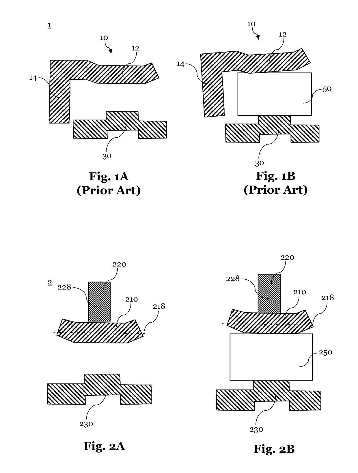
[0045]FIGS. 2A and 2B show a non-limiting example of an electrical terminal in a schematic cut view of the electrical terminal 2in which FIG. 2a shows the electrical terminal 2 without an inserted electrical pin 250. FIG. 2b shows the electrical terminal 2 with an inserted electrical pin 250. The electrical terminal 2 includes a body contact portion 230 for electrically contacting an electrical pin 250 when the electrical pin 250 is mated with the electrical terminal 2. Further, the electrical terminal 2 includes a contact blade 210 and an additional separate support blade 220. The support blade 220 and the contact blade 210 have the same material thickness, since they may be manufactured from the same kind of metal sheet. The contact blade 210 has a first sheet plane 218, and the support blade 220 has a second sheet plane 228. The first and second sheet planes 218, 228 are oriented substantially perpendicularly to each other.

[0046]Thus, when the electrical pin 250 is inserted into ...


PUM


Abstract

The present invention relates to an electrical terminal for a female connector. The terminal includes a contact blade having a first sheet plane. The contact blade is configured to contact an electrical pin with a contact force when the terminal is mated with the electrical and a separate support blade having a second sheet plane. The support blade engages with a corresponding contact blade to increase the contact force. The first and second sheet planes are orientated substantially perpendicular to each other.

Description

CROSS-REFERENCE TO RELATED APPLICATION[0001]This application claims the benefit under 35 U.S.C. §119(a) of Patent Application No. 15191746.5 filed in the European Patent Office on Oct. 27, 2015, the entire disclosure of which is hereby incorporated by reference.TECHNICAL FIELD OF THE INVENTION[0002]The invention relates to an electrical terminal for a female connector, preferably having small dimensions and a method to manufacture the same.BACKGROUND OF THE INVENTION[0003]There is a trend in the art to provide electrical connectors having smaller dimensions, for e.g. providing multiple connectors in a restricted building space. However, with the electrical connectors becoming smaller and smaller, the electrically conductive inlays of those electrical connectors, i.e. the male pins and / or the female terminals, have to become smaller as well.[0004]Wherein male pins can be manufactured with smaller dimensions (i.e. smaller cross section) very easily, it is more challenging to provide f...

Claims


Application Information

Patent Timeline
IPC IPC(8): H01R13/11H01R43/16
CPCH01R43/16H01R13/11H01R13/113H01R13/187H01R13/193
Inventor CORMIER, FRANCOISBOSSUYT, SYLVAINCAPPE, PATRICE
Owner APTIV TECH LTD
Why Eureka
Eureka Blog
Learn More